DRIVE SYSTEM
7-40 Rev. 000 TX525 Service Manual
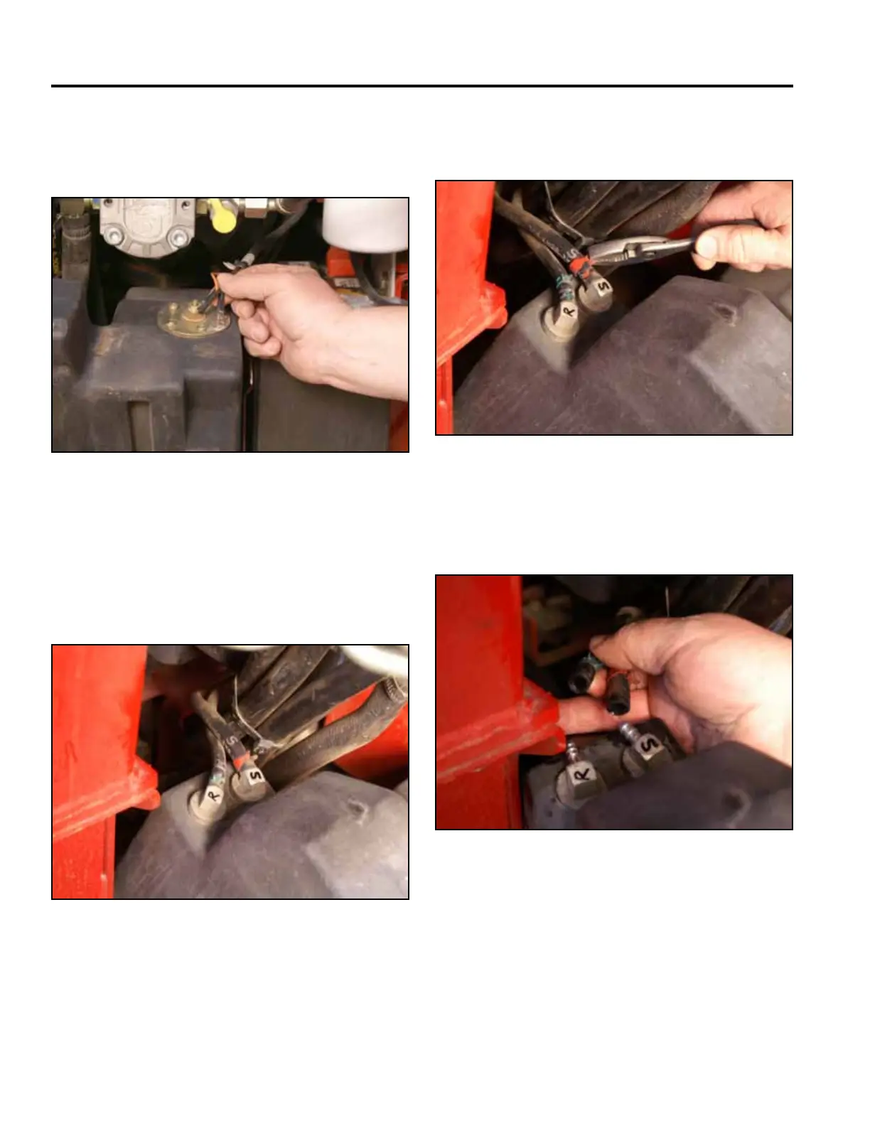
6. Disconnect the two wires (black and orange) from
the fuel sending unit located on the top of the fuel
tank (Fig. 1411).
Fig 1411 PICT-4262a
7. Markthesuctionfuellineandtankttingwithan“S”
andthereturnfuellineandtankttingwithan“R”
(Fig. 1412):
S - Fuel suction line
R - Fuel return line
Fig 1412 PICT-4263
8. Slide the 2 fuel hose clamps down the fuel lines
awayfromthefueltankttings(Fig.1413).
Fig 1413 PICT-4264
9. Slidethe2fuellinesoffthefueltankttings.Re-
move the fuel tank (Fig. 1414).
Fig 1414 PICT-4265

 Loading...


