ENGINE
4-22 Rev. 000 TX525 Service Manual
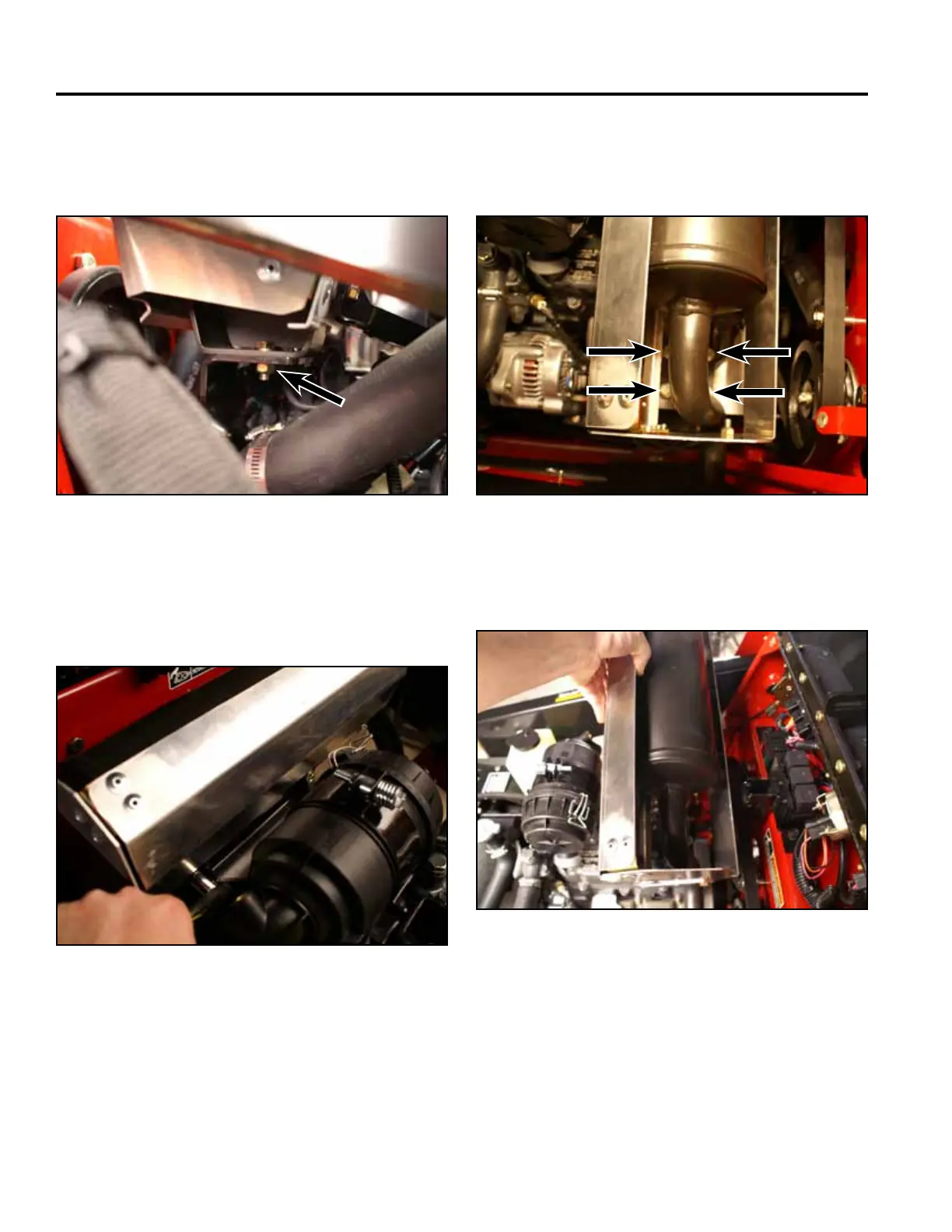
9. Removethemuferassembly(Fig.0159).
Fig 0159 PICT-3268
7. Usinga1/2”socketcombination,removethebolts
securingthemufertothefrontmuferbracket(Fig.
0157).
Fig 0157 PICT-3265
8. Usinga13mmsocketcombination,removethe4
boltsandwashersfromthemuferandexhaust
manifoldange(Fig.0158).
6. Usinga1/2”wrenchand1/2”socketcombination,
removetheboltandnutsecuringthebottomofthe
mufertotherearmuferbracket(Fig.0156).
Fig 0158 PICT-3266 Fig 0156 PICT-3263

 Loading...


