ENGINE
4-26 Rev. 000 TX525 Service Manual
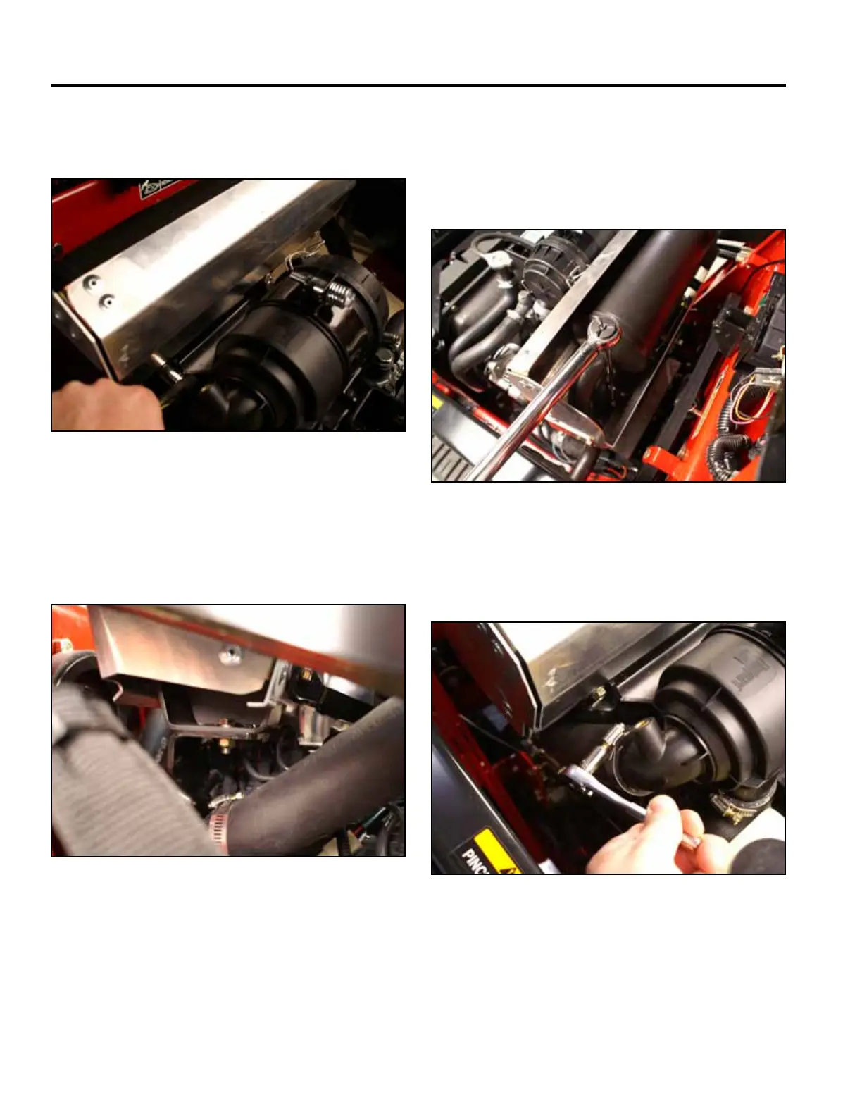
5. Looselyinstalltheboltsonthefrontmuferbracket
(Fig.0171).
Fig 0171 PICT-3265
6. Usinga1/2”wrenchand1/2”socketcombination,
installandtightentheboltandnutsecuringthe
bottomofthemufertotherearmuferbracket(Fig.
0172).
9. Positionandtightentheairintakehoseclamptothe
airlterassembly(Fig.0174).
Fig 0172 PICT-3263
Fig 0174 PICT-3259
10. Replacetherightandleftsidepanels.
7. Tightentheboltsonboththerearandfrontmufer
brackets.
8. Tightenandtorquetheexhaustmanifoldboltsto28
ft-lbs.(38Nm)(Fig.0173).
Fig 0173 PICT-3274

 Loading...


