Workman 1100/1110/2100/2110Page 6 – 12Electrical System
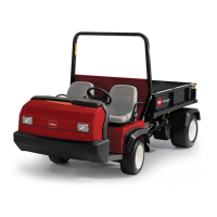
Accelerator Switch
The accelerator switch is a four terminal, two circuit
switch. When the accelerator pedal is pushed, the
switch allows current flow to the start/run solenoid, hour
meter, and engine oil indicator and provides an open cir-
cuit to the engine ignition system. With the accelerator
pedal released, the switch provides a grounding circuit
for the engine ignition system and prevents current flow
to the start/run solenoid, hour meter, and engine oil indi-
cator.
Testing
1. Place machine in the NEUTRAL position. Turn igni-
tion switch off, remove key from ignition switch, and en-
gage parking brake.
2. If equipped, remove floor mat from around pedal
area of machine.
3. Remove two screws that secure pedal cover to floor
of machine. Remove pedal cover to gain access to ac-
celerator switch.
4. Unplug wiring harness connector from switch.
5. With the use of a multimeter (ohms setting), the
switch functions may be tested to determine whether
continuity exists between the switch terminals for both
switch positions. Verify continuity between switch termi-
nals using the following table:
PLUNGER
POSITION
CONTINUITY
NO
CONTINUITY
IN 1 and 2 3 and 4
OUT 3 and 4 1 and 2
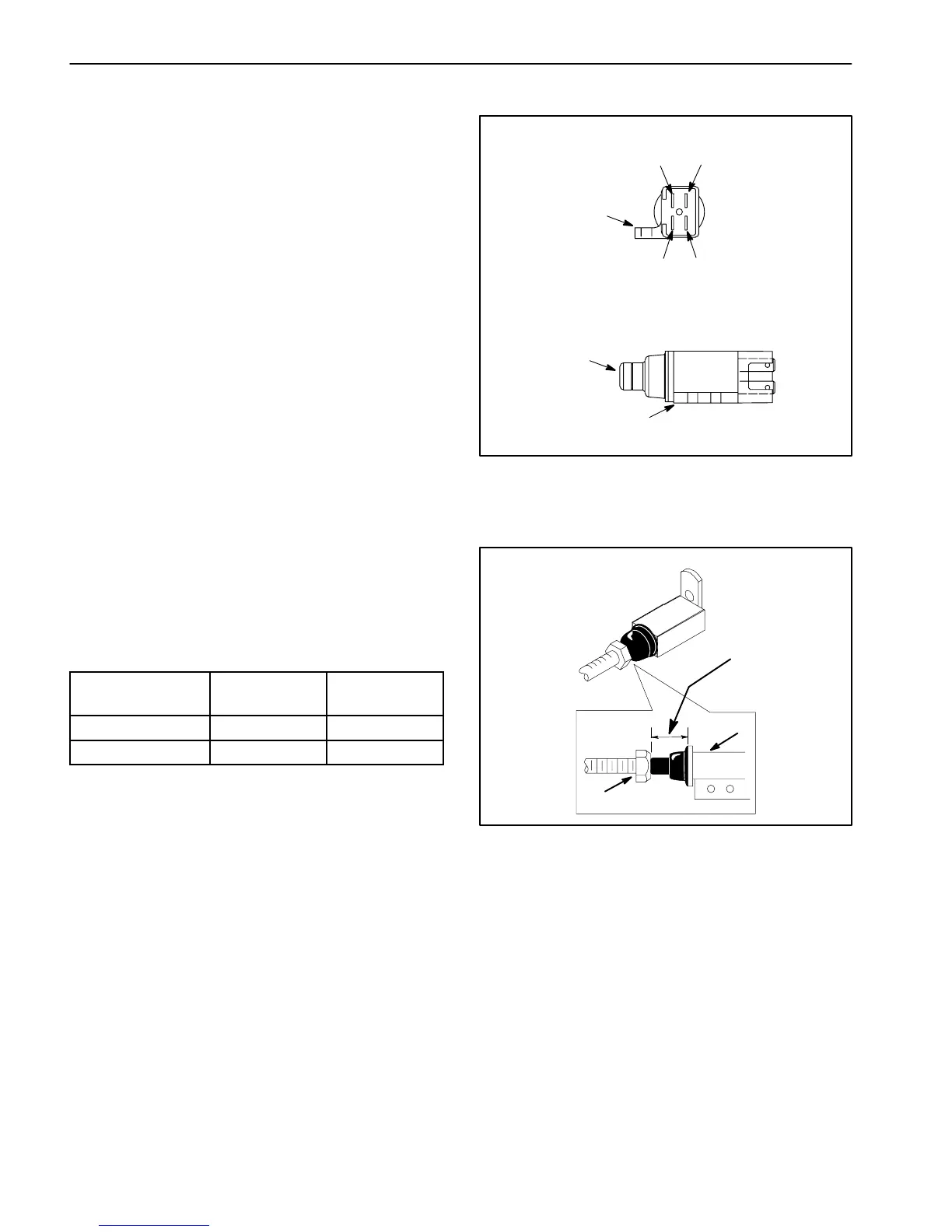
Adjustment
1. Release the parking brake.
2. With the accelerator pedal released, adjust the dis-
tance between the head of the accelerator switch bolt
and the body of the switch to 5/8 inch (1.6 cm) (Fig. 14).
3. After switch adjustment, make sure that the engine
starter does not engage when the parking brake is en-
gaged. If starter does engage when parking brake is set,
accelerator switch should be readjusted by reducing the
distance between the head of the accelerator switch bolt
and the body of the switch slightly.
4. After final switch adjustment, make sure that switch
plunger is not bottomed out when accelerator pedal is
released.
1. Terminal 1
2. Terminal 2
3. Terminal 3
4. Terminal 4
5. Switch plunger
6. Mounting tab
Figure 13
2
1
3
5
6
END VIEW
SIDE VIEW
4
6
1. Switch bolt 2. Accelerator switch
Figure 14
1
2
5/8 inch
(1.6 cm)

 Loading...