Workman 1100/1110/2100/2110Page 7 – 42Chassis, Wheels, and Brakes (Rev. B)
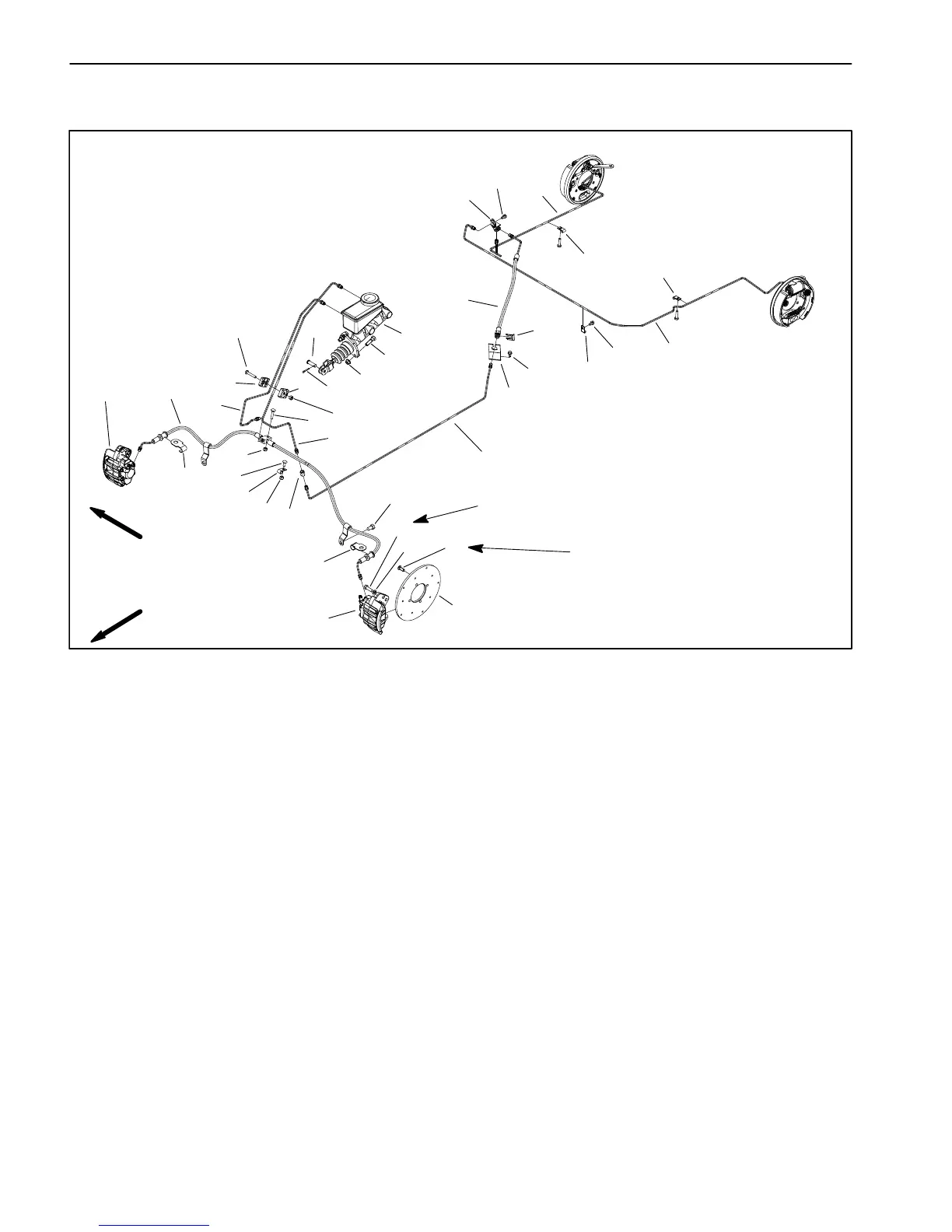
Hydraulic Brake System (Workman 1110 and 2110)
1. Brake caliper (LH)
2. Brake caliper (RH)
3. Brake rotor
4. Front brake tube
5. Front brake hose
6. Carriage screw
7. Rear brake tube
8. Carriage screw
9. Rear brake hose bracket
10. Cap screw
11. Thread formin
23. Rear brake tube
24. Rear brake hose
25. Hose bracket
26. Tube clamp
27. Clamp
28. Cap screw (2 per caliper used)
29. Lock washer (2 per caliper used)
30. Socket head screw (4 per rotor used)
31. Cap screw
32. Lock nut
Figure 28
2
25
31
30
3
1
28
29
25
32
27
8
32
7
6
32
26
20
18
17
21
9
12
11
16
11
15
16
16
14
11
13
10
26
4
5
19
22
23
24
FRONT
RIGHT
18 ft–lb
(24 N–m)
Thread locking
Compound
When performing service work on the Workman 1110
and 2110 hydraulic brake system, make sure to clean
components before disassembly. Use Figure 28 as a
guide for removal and installation of hydraulic brake
components.

 Loading...