Workman 1100/1110/2100/2110
Drive Train
Page 5 -- 12
Driven Clutch
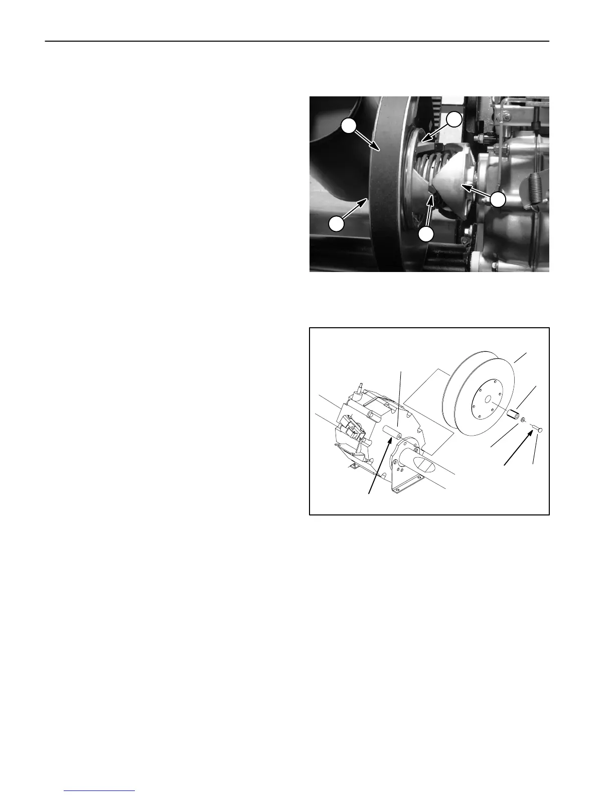
Principles of Operation (Fig. 17)
The operation of the driven clutch is affected by trans-
axle load. When the vehicle is s topped, the drive belt is
held at the outer diameter of the clutch sheaves from the
pressure of the spring pushing the moveable sheave
against the fixed sheave and away from the fixed cam.
Three sets of buttons on the moveable sheave provide
a low friction surface on which the sheave can slide on
therampofthefixedcam.
Once the drive belt starts rotating, the drive clutch also
starts to rotate. With increasing speed of the drive
clutch, the drive belt begins to climb to the outer diame-
ter of its sheaves. This increases the tension on the drive
belt, and forces the moveable sheave to move away
from the fixed sheave against the pressure of the spring.
As the belt tightens and the sheaves open up, the drive
belt rides lower in the clutch sheaves.
With increased load to the transaxle, the cam resists for-
ward movement relative to the moveable sheave and
drive belt. Torque from the drive belt and spring pressure
moves the movable s heave up the ramp of the fixed
cam. The drive belt becomes positioned closer to the
outer diameter of the clutch sheaves.
Removal (Fig. 18)
1. Park machine on a level surface, stop engine, set
parking brake, and remove key from the ignition switch.
2. Remove muffler from the engine and engine mount
(see Muffler Removal in Engine Chapter).
3. Remove drive belt from the driven clutch (see Ser-
vice Drive Belt in Service and Repairs section of Engine
Chapter).
4. Remove cap screw, washer, and spacer (if
equipped) securing the driven clutch to the input shaft of
the transaxle.
5. Pull driven clutch from the input shaft.
Installation (Fig. 18)
1. Coat input shaft of the transaxle with never seize lu-
bricant.
2. Position driven clutch to the input shaft. Make sure
pulley side of the clutch faces away from the transaxle
case.
3. Apply Loctite #242 (blue) (or equivalent) to the cap
screw threads.
1. Moveable sheave
2. Ramp (fixed cam)
3. Button
4. Fixed sheave
5. Drive belt
Figure 17
3
2
1
5
4
1. Cap screw
2. Washer
3. Spacer (if equipped)
4. Driven clutch
5. Input shaft (transaxle)
Figure 18
1
2
4
3
5
Loctite #242
Never seize

 Loading...