Workman 1100/2100/2110 Drive TrainPage 5 – 45
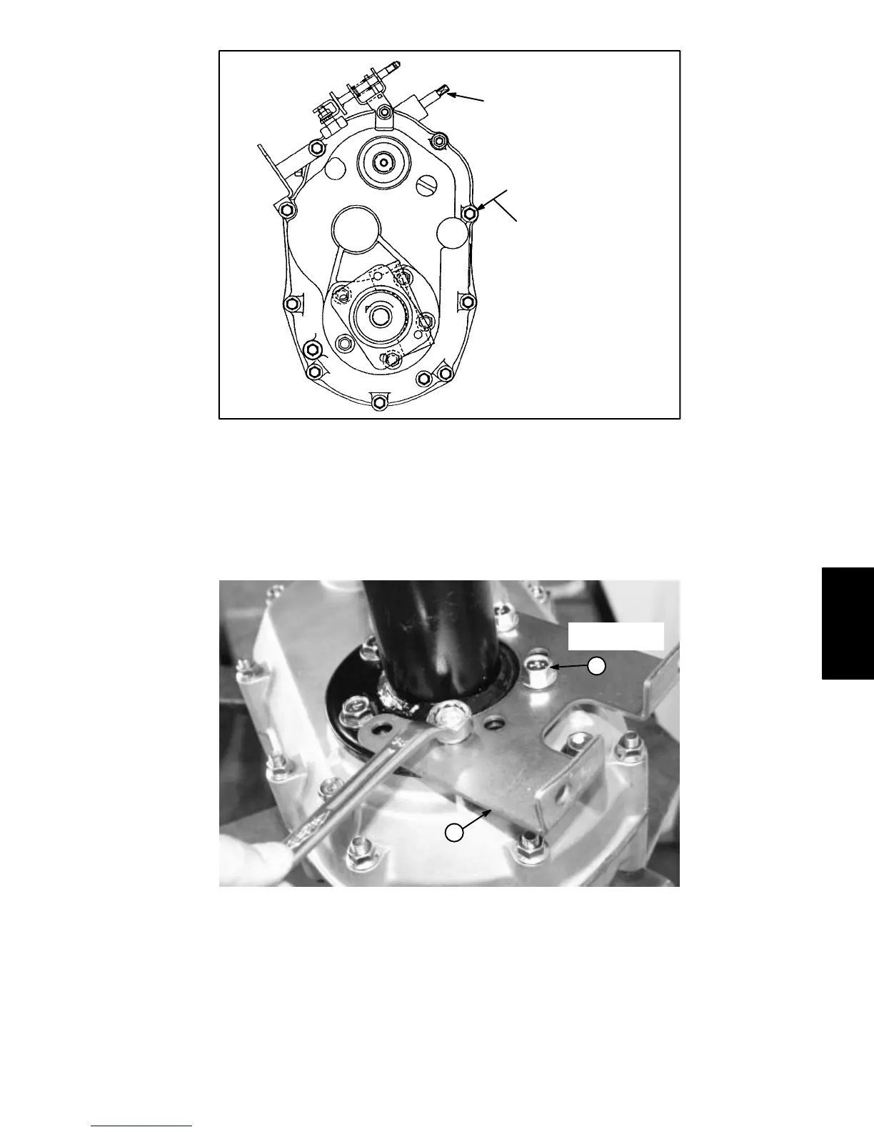
1. Governor shaft 2. Bolt
Figure 75
2
1
15 to 18 ft–lb
(21 to 25 N–m)
Note: When installing case (RH) to the case (LH), hold
governor shaft so the ball bearing will not drop off. Keep
the gasket sealing surfaces of the cases as horizontal to
each other as possible. If the sealing surfaces do not join
to each other, tap the case lightly with a plastic hammer.
C. Install case (RH) so each shaft fits properly into
the case.
D. Secure case (RH) to case (LH) with bolts. Torque
bolts from 15 to 18 ft–lb (21 to 25 N–m).
1. Axle bracket 2. Flange bolt
Figure 76
25 to 31 ft–lb
(34 to 42 N–m)
1
2
E. Position axle bracket to each axle case. Secure
axle bracket to each axle case with flange bolts.
Torque bolts from 25 to 31 ft–lb (34 to 42 N–m).
Drive
Train

 Loading...