Workman 1100/2100/2110
Drive Train
Page 5 – 10
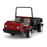
1. Fixed sheave
2. Spring
3. Washer
4. Spider assembly
5. Cap screw
6. Plastic cap
7. Cover
8. Moveable sheave
9. Roller kit
10. Cam weight
11. Nut
12. Pilot bolt
Figure 10
1
2
3
4
5
6
7
8
9
10
11
12
100 ft–lb
(136 N–m)
75 to 100 in–lb
(8.5 to 11.3 N–m)
Disassembly (Fig. 10)
IMPORTANT: Do not pry off cover, damage may re-
sult. Cover should pop off.
1. Remove cap screws securing the cover to the mov-
able sheave. Pull cover from clutch.
2. Remove the engine pulley from the drive clutch. Re-
move four cap screws and lock washers securing the
pulley and starter spacer to the clutch.
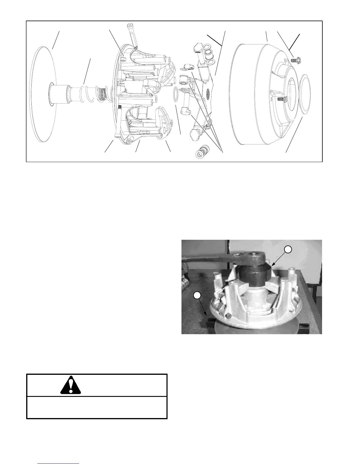
3. Use two 1/4–20 X 1” cap screws to secure the spider
removal holding bar (TOR4098: see Special Tools) to
drive clutch (Fig. 11).
4. Place clutch with attached spider removal holding
bar into vise.
5. Matchmark position of spider and moveable sheave
for reassembly.
IMPORTANT: Use spider removal tool kit to remove
spider. Unequal pressure on the cam towers may
damage them.
CAUTION
Remove spider from fixed sheave slowly. The
moveable sheave is under pressure from the
spring.
6. Using spider removal spanner tool (TOR4098: see
Special Tools), remove spider from the fixed sheave
post (Fig. 11).
1. Holding bar 2. Spanner
Figure 11
1
3
2
4
2
1

 Loading...