Workman 1100/1110/2100/2110 Page 6 – 13 Electrical System
Diode Assembly
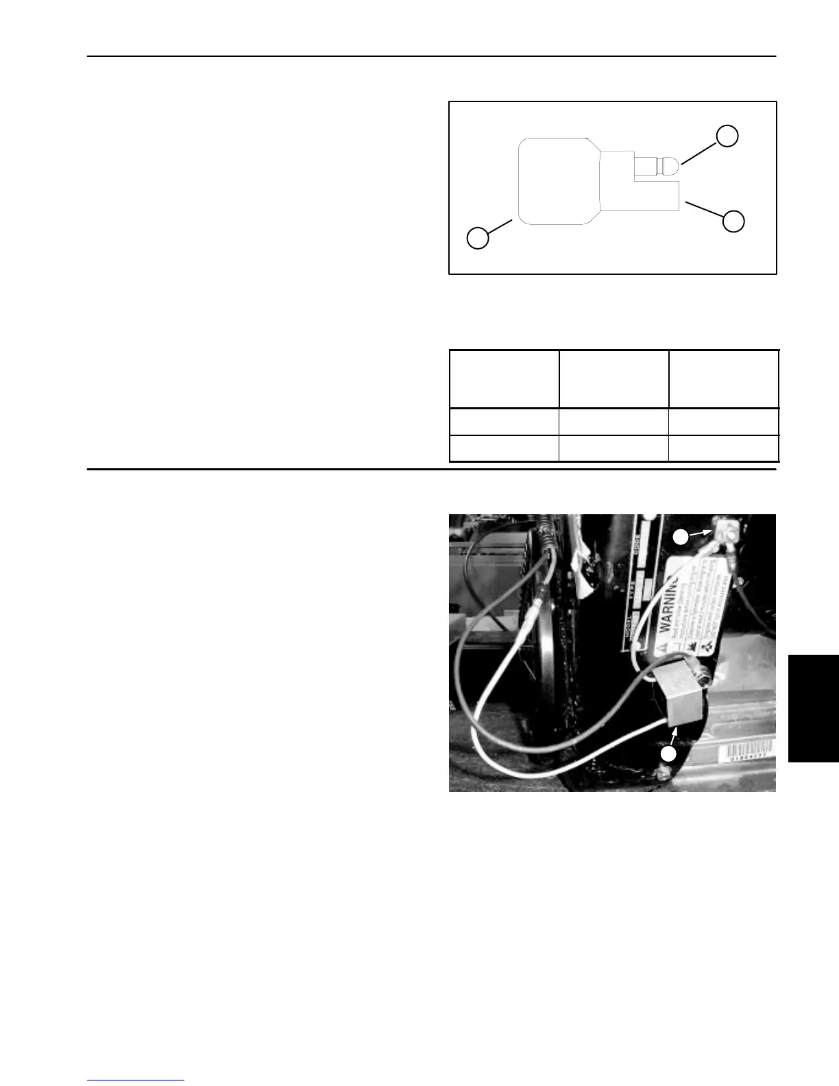
The diode D1 (Fig. 15) is used to protect the ignition
switch from voltage spikes that can occur when the start-
er solenoid is de–energized. The diode plugs into the
wiring harness.
Testing
The diode can be tested using a digital multimeter
(diode test or ohms setting) and the table to the right.
Figure 15
1
1. Diode
2. Male terminal
3. Female terminal
3
2
Multimeter
Red Lead (+)
on Terminal
Multimeter
Black Lead (–)
on Terminal
Continuity
Female Male YES
Male Female NO
RPM Shutdown Module (Workman 2100/2110)
The RPM shutdown module allows the engine to contin-
ue running briefly after the accelerator pedal is released
and the vehicle is decelerating. The module monitors
engine speed at the engine stop switch terminal.
Through the RPM shutdown module, the engine ignition
system is not grounded until the engine speed has
slowed to approximately 1300 RPM. By allowing the en-
gine to continue running briefly during vehicle decelera-
tion, better vehicle performance can be achieved.
Testing
1. Make sure that accelerator switch is working correct-
ly and is adjusted properly (see Accelerator Switch).
2. Place drive system in the NEUTRAL position (see
Operator’s Manual).
3. Connect an ignition spark tester in series between
spark plug and spark plug wire.
4. Start engine and monitor engine speed with a
tachometer. Press the accelerator pedal to raise engine
speed briefly and then release pedal while watching
tachometer and spark tester. When engine speed de-
creases to approximately 1300 RPM, spark tester
should register no spark and the engine should stop.
1. RPM shutdown module 2. Stop switch terminal
Figure 16
1
2
Electrical
System

 Loading...