Rev. B
Workman 2100/2110Page 3 – 6Briggs & Stratton Gasoline Engine
Adjustments
Adjust Starter/Generator Belt
Note: Perform this maintenance procedure at the in-
terval specified in the Operator’s Manual or Chapter 2
– Product Records and Maintenance.
1. Park machine on a level surface, stop engine, en-
gage parking brake, and remove key from the ignition
switch.
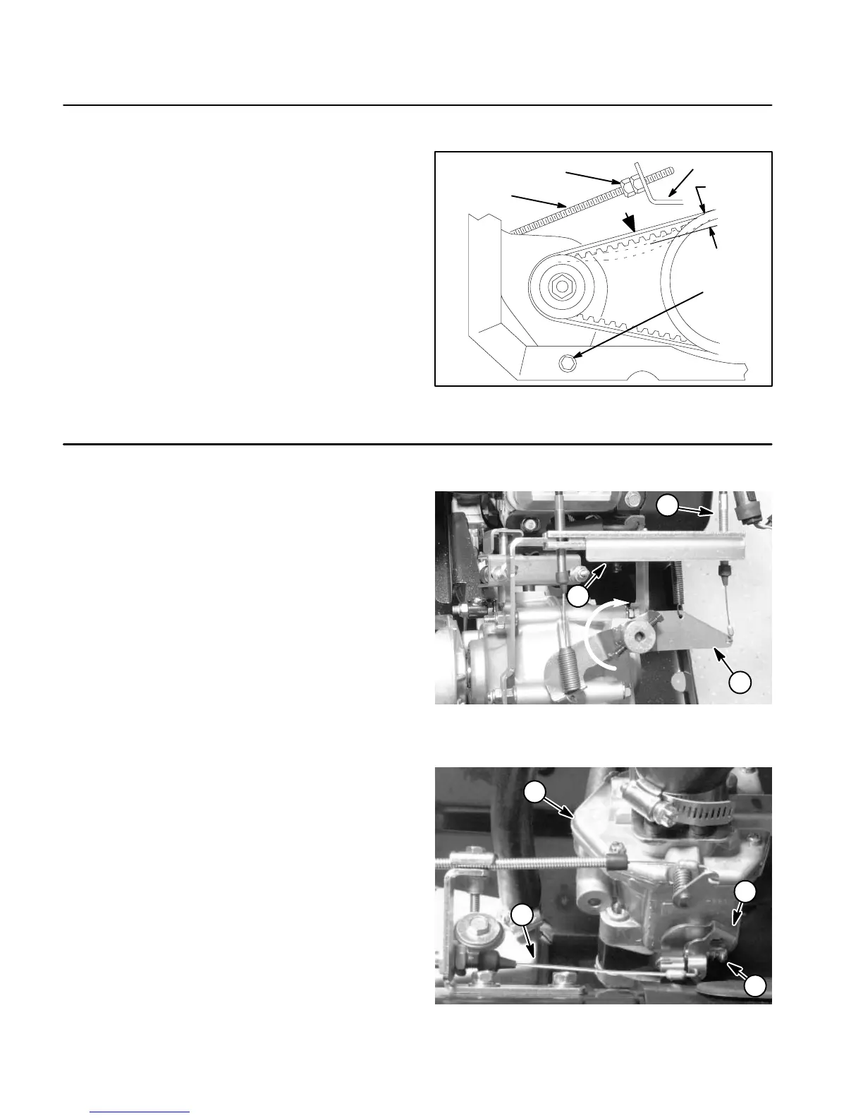
2. Loosen starter generator pivot bolt.
3. While pressing the belt at mid–span between the pul-
leys with 10 lb (44.5 N) of force, adjust jam nut on the
starter rod until the belt flexes 1/4 inch (6 mm).
4. Tighten starter generator pivot bolt.
Figure 4
1. Generator pivot bolt
2. Jam nut
3. Starter rod
4. Torque arm
1
2
10 lbs.
1/4”
3
4
Adjust Throttle Cable
Note: Workman 2100 and 2110 machines with Serial
Numbers above 240000000 are equipped with an en-
gine governor rather than a transaxle governor. Refer to
the Briggs & Stratton Repair Manual at the end of this
chapter for governor information on these machines.
Releasing the accelerator pedal should allow the throttle
cable to close the carburetor throttle control lever so that
the lever touches the adjustment screw. The adjustment
screw keeps the throttle valve inside the carburetor
open slightly to prevent the valve from binding.
1. Park machine on a level surface, stop engine, en-
gage parking brake, and remove key from the ignition
switch.
2. Lift cargo bed and prop with rod to gain access to the
engine.
3. Rotate governor arm on transaxle fully clockwise
(Fig. 5).
4. Make sure of the following:
A. The engine throttle control lever should be to the
fully open position (Fig. 6).
B. Adjust throttle cable at the cable bracket as nec-
essary, so there is no compression of the throttle
cable (Fig. 5). This will allow the throttle control lever
to fully close when the accelerator pedal is released.
Figure 5
1. Governor arm
2. Throttle cable
3. Cable bracket
3
1
2
Figure 6
1. Carburetor
2. Throttle cable
3. Adjustment screw
4. Throttle control lever
3
1
2
4

 Loading...