Rev. A
Workman 1100/2100/2110 Drive TrainPage 5 -- 11
Inspection
1. Inspect the tapered ends of the crankshaft and pri-
mary fixed sheave for scratches. If either is severely
scratched, replace component. If scratches are minor,
burnish the component with emery cloth.
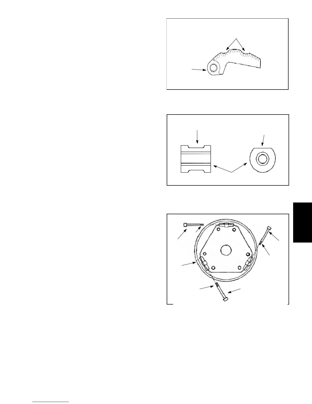
2. Check the surface of the cam weights. If worn, re-
place all cam weights as a set (Fig. 14).
3. Check the rollers. If binding or uneven wear is found,
replace all rollers as a set (Fig. 15).
4. Clean pilot bolts and roller pins with 800 -- 1000 grit
abrasive paper. If the chrome--plated surface of the bolts
or pins is scaled off, replace the damaged components.
5. Check the contact surface of the movable sheave for
wear and/or fraying. If surface is worn/frayed, replace
component.
6. Inspect the clutch spring and replace if damaged or
fatigued.
Assembly (Fig. 12)
1. If removed, install rollers, washers, and roller pins to
spider. Roller pins should be lubricated with Toro part
#104--7011 (or equivalent).
2. Lubricate cam weights with Toro part #104--7011 (or
equivalent). Make sure lubricant penetrates to pilot bolts
by rotating and sliding the weights side to side, or re-
move weights if needed to lubricate properly. Assemble
cam weights to moveable s heave as follows:
A. Make sure the threads of the pilot bolts are clean
and dry. Apply Loctite #271 (or equivalent) to the
threads of each bolt.
IMPORTANT: To maintain the balance of the clutch,
all pilot bolts must be installed with their threads
pointing in a clockwise direction (Fig. 16).
B. Immediately install new self locking nuts on the
pilot bolts. Tighten nuts until they just touch the
sheave casting. Never reuse self--locking nuts.
3. Apply Loctite #271 (or equivalent) to the threads of
the fixed sheave post.
4. Install s pider to the fixed sheave post using spider re-
moval tool kit (TOR4098: see Special Tools). Make sure
to align matchmark.
5. Torque spider to 100 ft--lb (136 N --m).
6. Position cover to clutch. Secure cover to the mov-
able sheave with cap screws. Torque cap screws from
75 to 100 in--lb (8.5 to 11.3 N--m).
1. Cam weight 2. Worn contact surface
Figure 14
2
1
1. Roller
2. Wei
ht contact surface
3. Roller uneven wear
Figure 15
1
3
2
1. Pilot bolt
2. Pilot bolt threads
3. Moveable sheave
Figure 16
1
1
1
2
3
2
2
Drive
Train

 Loading...