E6581697
B-6
2
2.3 Description of terminals
2.3.1 Power circuit terminals
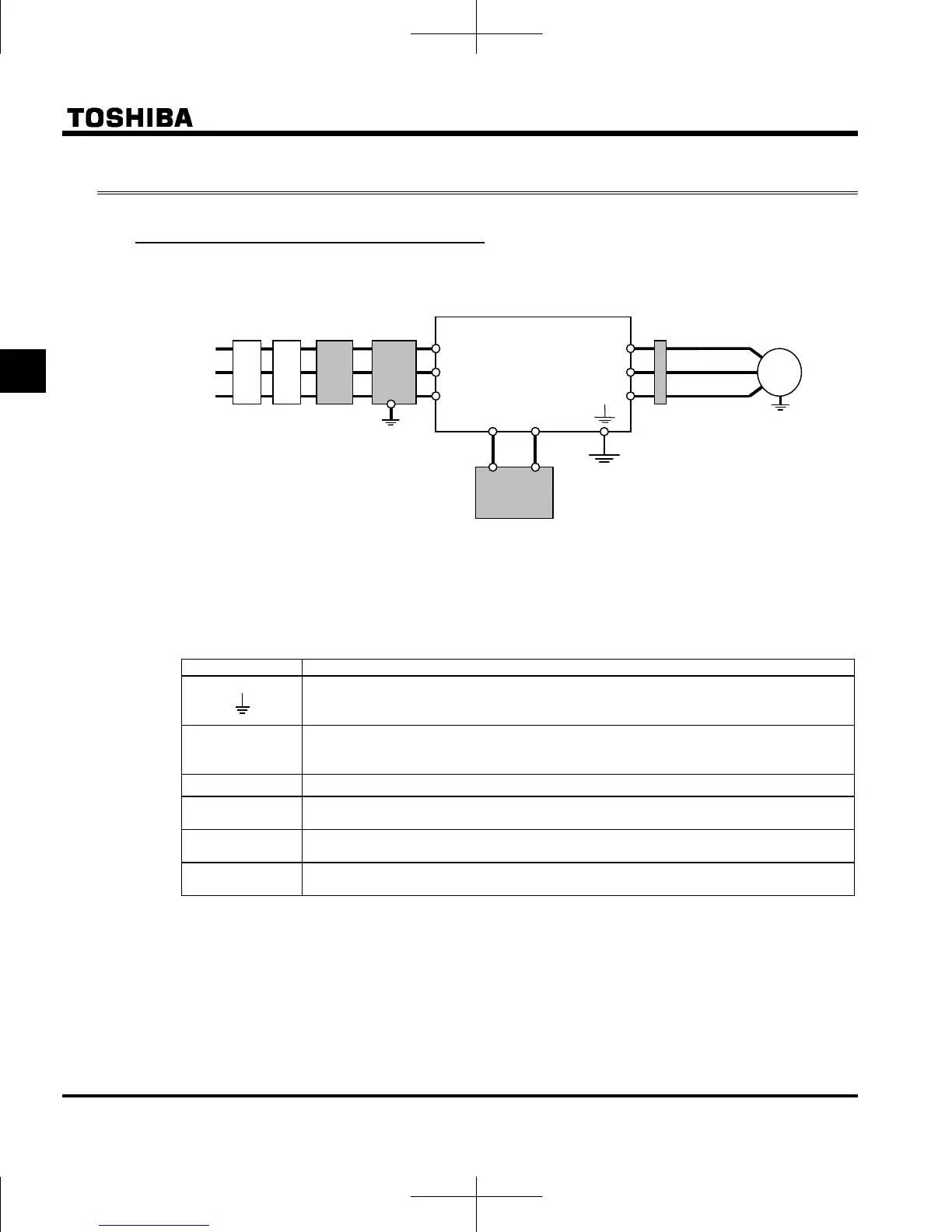
■ Connections with peripheral equipment
Motor
Power
supply
Inverter
Braking resistor
No-fuse
braker
R/L1
S
L2
T/L3
PBe
PB
V
T2
U/T1
W/T3
M
Magnetic
contactor
Input AC
reactor
noise
reduction filter
Zero-phase
reactor
Note 1: The T/L3 terminal is not provided for any single-phase models. So if you are using single-phase
models, use the R/L1 and S/L2/N terminals to connect power cables.
■ Power circuit
Terminal symbol Terminal function
Grounding terminal for connecting inverter. There are 3 terminals in total.
Up to 4.0kW : 2 terminals on upper side, 1 terminal on down side.
5.5 to 15kW : 3 terminals on down side.
R/L1,S/L2,T/L3
240V class: Single-phase 200 to 240V-50/60Hz
500V class: Three-phase 380 to 500V-50/60Hz
* Single-phase inputs are R/L1 and S/L2/N terminals.
U/T1,V/T2,W/T3
Connect to three-phase motor.
PBe, PB
Connect to braking resistors.
Change parameters , , , if necessary.
PA/+
This is a positive potential terminal in the internal DC main circuit.
DC common power can be input with PC/- terminal.
PC/-
This is a negative potential terminal in the internal DC main circuit.
DC common power can be input with PA/+ terminal.
The arrangements of power circuit terminals are different from each range.
Refer to section 1.3.3.1) for details.
 Loading...