E6581697
B-7
2
2.2
+24V
2.2k
470
F
R
RES
S1
EXT
SW1
SINK
SOURCE
S2
27.4
S3
27.4
+5V
1k
+5V
27.4
27.4
15
+5V
+5 V
1k
1k
SW2
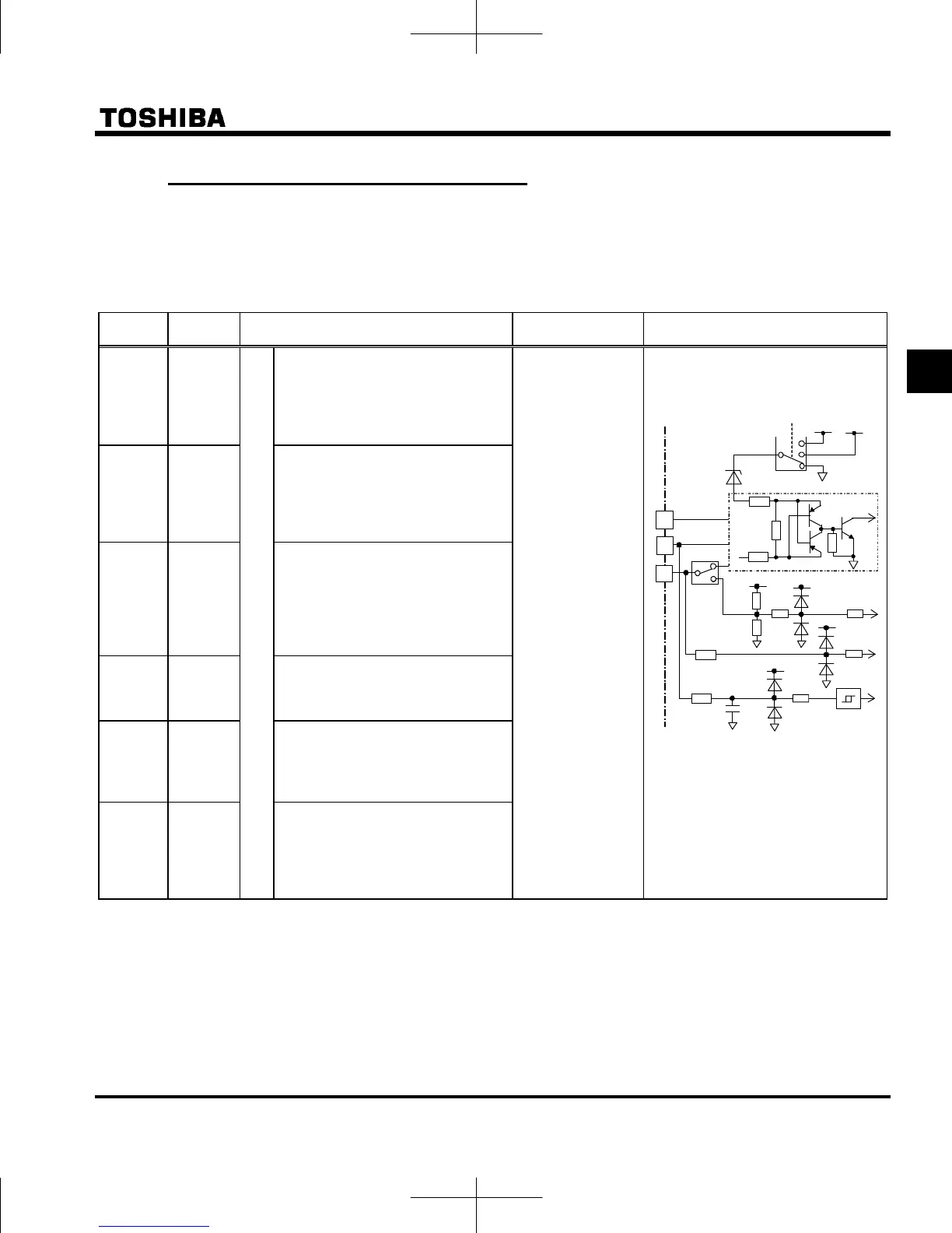
2.3.2 Control circuit terminals
The control circuit terminal board is common to all equipment.
Regarding to the function and specification of each terminal, please refer to the following table.
Refer to section 1.3.3.3) about the arrangement of control circuit terminals.
■ Control circuit terminals
Terminal
symbol
Input /
output
Function
Electrical
specifications
Inverter internal circuits
F Input
Shorting across F-CC or P24-F
causes forward rotation; open
causes deceleration stop.
(When Standby ST is always ON)
3 different functions can be
assigned.
R Input
Shorting across R-CC or P24-R
causes reverse rotation; open
causes deceleration stop.
(When Standby ST is always ON)
3 different functions can be
assigned.
RES Input
This inverter protective function is
reset if RES-CC or P24-RES is
connected. Shorting RES-CC or
P24-RES has no effect when the
inverter is in a normal condition.
2 different functions can be
assigned.
S1 Input
Shorting across S1-CC or P24-S1
causes preset speed operation.
2 different functions can be
assigned.
S2 Input
Shorting across S2-CC or P24-S2
causes preset speed operation.
By changing parameter f146
setting, this terminal can also be
used as a pulse train input terminal.
S3 Input
Multifunction programmable logic input
Shorting across S3-CC or P24-S3
causes preset speed operation.
By changing slide switch SW2 and
parameter f147 setting, this
terminal can also be used as a PTC
input terminal.
No voltage
logic input
24Vdc-5mA or less
Sink/Source and
PLC selectable
using slide switch
SW1
(Left column is
in sink logic)
(Default setting is
PLC side)
Pulse train input
(S2 terminal)
Pulse frequency
range:
10pps~20kpps
PTC input
(S3 terminal)
PTC type: PT100
 Loading...