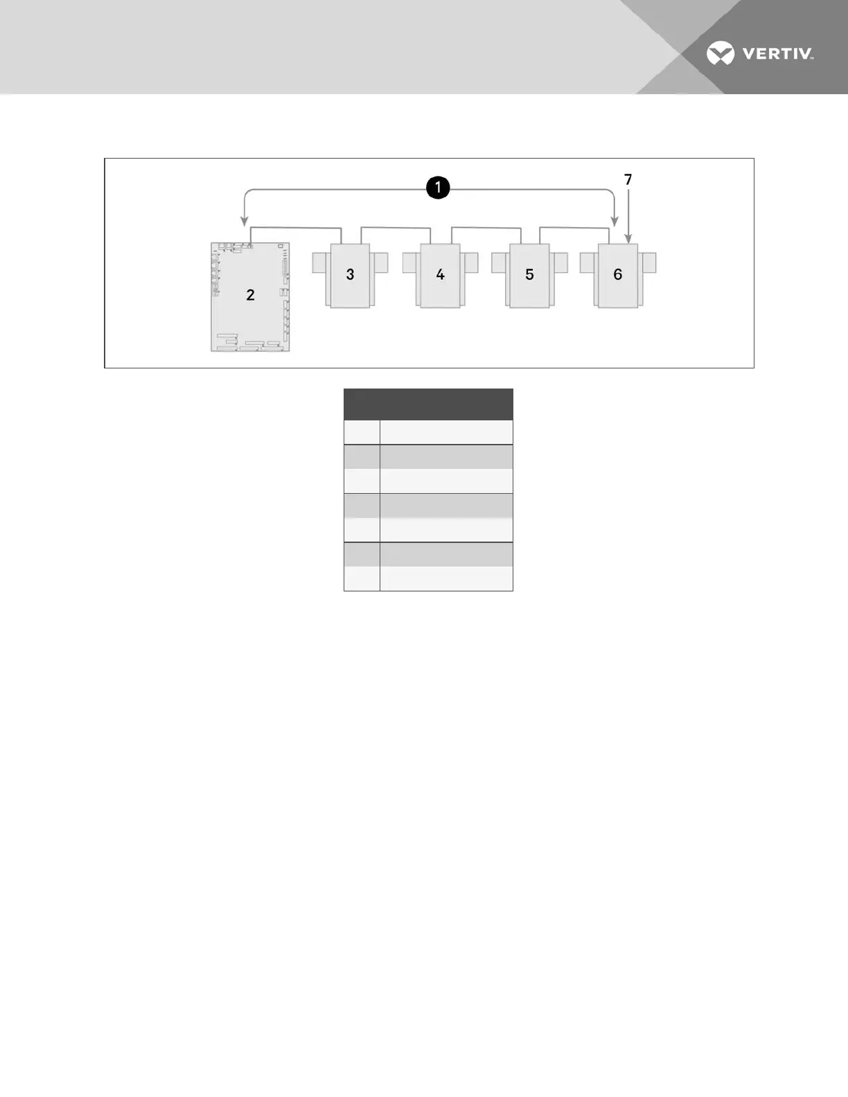
Figure 12.7 Example Sensor CANbus Arrangement
Item Description
1 CANbus communication loop
2 iCOM control board
3 2T sensor
4 2T sensor
5 2T sensor
6 2T sensor
7 Terminated sensor
To terminate the last sensor:
1. Locate the sensor that will be last on the network.
NOTE: The last sensor on the network will be the sensor with only 1 CAN cable after all sensors are connected to the
CANbus network. See Connect the CANbus Cable and Ground on page117.
2. Open the sensor’s case by removing the Phillips-head screws (typically 3) on the rear of the housing to access
the jumper used for terminating.
3. Remove the black jumper from pins 1 and 2 on the P3 pin connector, and install it on pins 2 and 3 as shown in
Figure 12.8 on the next page.
4. Replace the sensor cover.
The 2T sensor is terminated in the CANbus link.
13 Hardware Installation
113
 Loading...