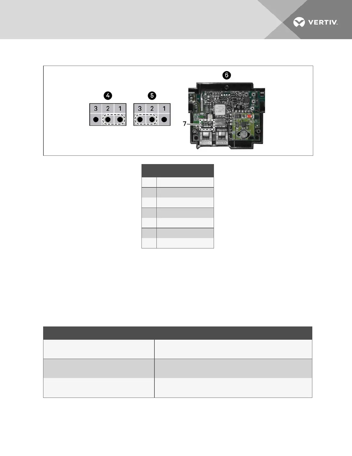
Figure 12.18 Termination Jumper on 2T Circuit Board
Item Description
1 Position 1 (P3 jumper)
2 Position 2 (P3 jumper)
3 Position 3 (P3 jumper)
4 Unterminated
5 Terminated
6 Rear of sensor, cover removed
7 P3 termination jumper
13.4 Installing Analog Input Devices
External sensors and analog devices may be connected to iCOM using an electrical connection on the iCOM control board
to a required, factory supplied plug, harness and terminal strip. (Contact Vertiv™ technical support for parts.)
When equipped, devices as follows can be connected to terminals 41, 42, 43 and 44, 45 and 46, or 47 and 48. Table 12.5
below, lists available analog inputs depending on the type of cooling unit.
See Configuring Analog Input Devices on page84, to configure the iCOM settings for the device.
Cooling unit Inputs available
Liebert® CW™ and Liebert® PCW™ with MBV
4
2 may be used for valve feedback on CW, 1 on Liebert® PCW.
Liebert® CW and Liebert® PCW with3P(floating
pointactuator)
4
2 may be used for valve feedback on CW, 1 on Liebert® PCW.
Liebert® DS™ and Liebert® DSE™ Air-cooled
2
Both used for low pressure transducers.
Table 12.5 Number of Analog Inputs Available by Cooling Unit Type
13 Hardware Installation
125
 Loading...