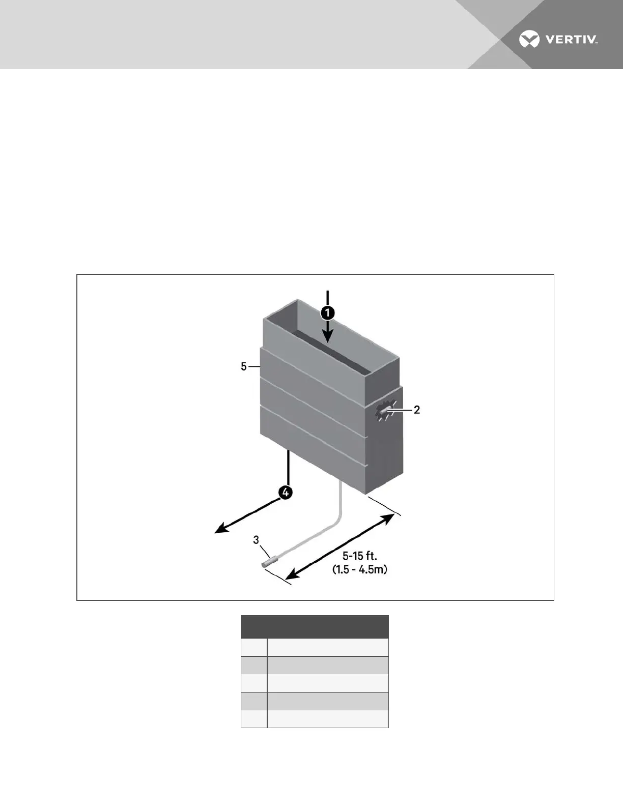
13.3 Installing Supply Control Sensors
13.3.1 Installing the Supply Air Temperature Sensor
The supply temperature sensor is connected to P8, Pins 1 and 2 at the factory require no configuration.
1. Place the sensor in an area that is influenced only by the unit to which it is connected to provide an accurate
reading: 5ft. to 15ft. (1.5m to 4.5m) from the cooling unit, Figure 12.15 below.
NOTE: A 50 ft. (15 m) extension cable is available from Vertiv™ if the sensor must be more than 15ft.(4.5m) from the
iCOM unit.
2. Confirm connectivity via SENSOR DATA. See Viewing Sensor Data on page17.
Figure 12.15 Placement of the Supply Air Temperature Sensor
Item Description
1 Return air
2 Internal temperature/humidity sensor
3 Temperature sensor
4 Supply air
5 Liebert® Thermal Management unit
13 Hardware Installation
121
 Loading...