3. Referring to Table 12.2 below, and using the non-conductive tool, set the DIP switches for each sensor to its
number in the chain (from sticker applied in step 1).
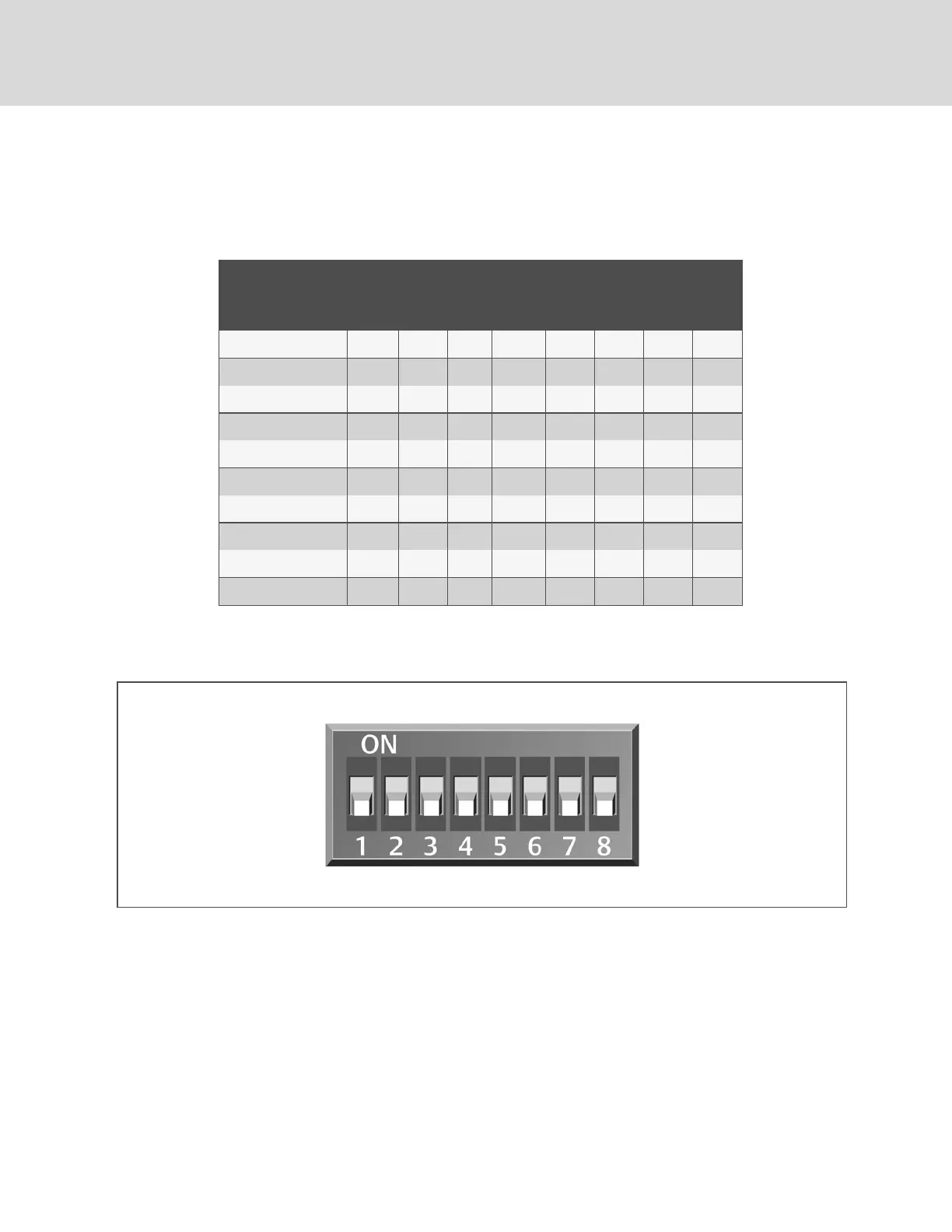
Figure 12.6 below, shows a representation of the DIP switches.
4. Confirm that the DIP switches are set correctly for each sensor, and replace the housing cover if necessary.
2T sensor
number/address
DIP-switch position
1 2 3 4 5 6 7 8
1 Off Off On Off On Off Off Off
2 On Off On Off On Off Off Off
3 Off On On Off On Off Off Off
4 On On On Off On Off Off Off
5 Off Off Off On On Off Off Off
6 On Off Off On On Off Off Off
7 Off On Off On On Off Off Off
8 On On Off On On Off Off Off
9 Off Off On On On Off Off Off
10 On Off On On On Off Off Off
Table 12.2 DIP Switch Settings for Wired Remote Sensors
NOTE: Up is on, down is off on the DIP switch.
Figure 12.6 DIP Switches in 2T Sensor
13.1.2 Terminating the Last Sensor on the CANbus Link
The 2T sensor need not be installed in the numeric order of their address/sensor number (although it may be easier for later
maintenance). However, the last sensor in the chain must be terminated. All others must remain unterminated. We also
recommend that you make a record of the sensor numbers along with the name/number of the rack on which they are
installed. Figure 12.7 on the facing page, shows an example CANbus arrangement.
NOTE: To add sensors, unterminate final sensor, add sensors to the chain, and terminate the new final sensor.
Vertiv™ | Liebert® iCOM™Installer/User Guide
112
 Loading...