NOTE: Sensors are connected in a daisy chain via CANbus cabling to the cooling-unit control board. You can extend
the sensor network (up to 10) by adding sensors to the end of the chain and adjusting the termination settings. Do not
run individual wires from the sensors to the cooling unit.
1. Apply numbered stickers to the sensor housing that corresponds to the sensor’s position in the chain.
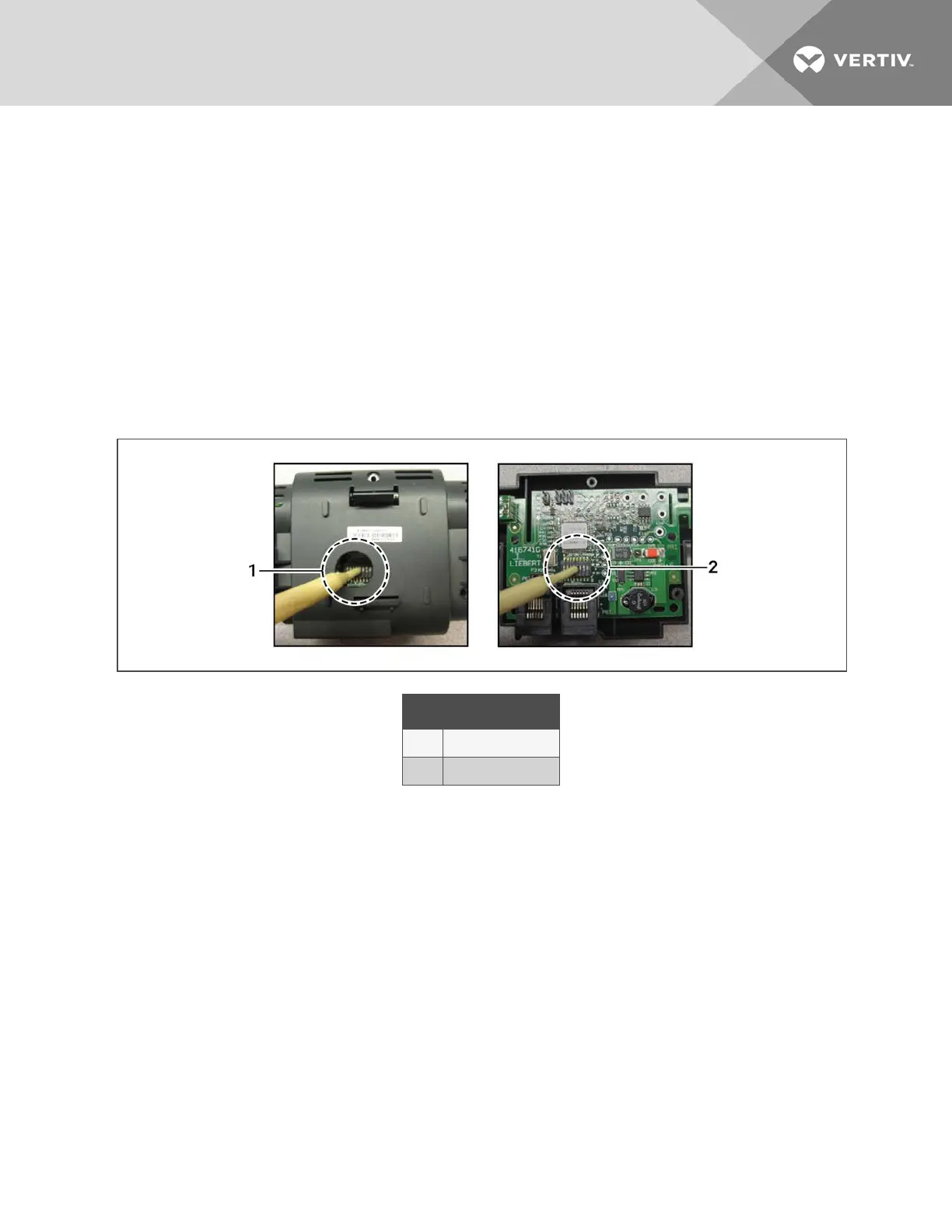
2. Locate the DIP-switch hole on the rear of the sensor housing, Figure 12.5 below.
– or –
If the hole is not present, or the settings are difficult to make through the hole, remove the cover by removing
the Phillips-head screws (typically 3). See Figure 12.5 below.
NOTE: Use the non-conductive DIP-switch tool (included) or a similar tool to set switches. Do not insert any metal
object into the sensor case.
Figure 12.5 DIP Switch Opening/DIP Switches Inside of 2T Sensor
Item Description
1 Hole in sensor housing
2 Cover removed
13 Hardware Installation
111
 Loading...