7. Read and record all programmed settings for each of the individual units (see Backing Up, Importing,
Exporting, and Restoring Display Settings on page91).
8. Verify that network cabling and switches are provided, ready to connect, and labeled by unit at the network
switch.
NOTE: Cooling units are factory wired for stand alone operation. Do not connect the U2U network cabling before
setting the U2U network configuration/groups. Network communication conflicts and unreliable display readings will
result. Configure the network using Configuring U2U Network Settings on the facing page, then refer to U2U Wiring
connection on page127, to connect the network cabling and hardware.
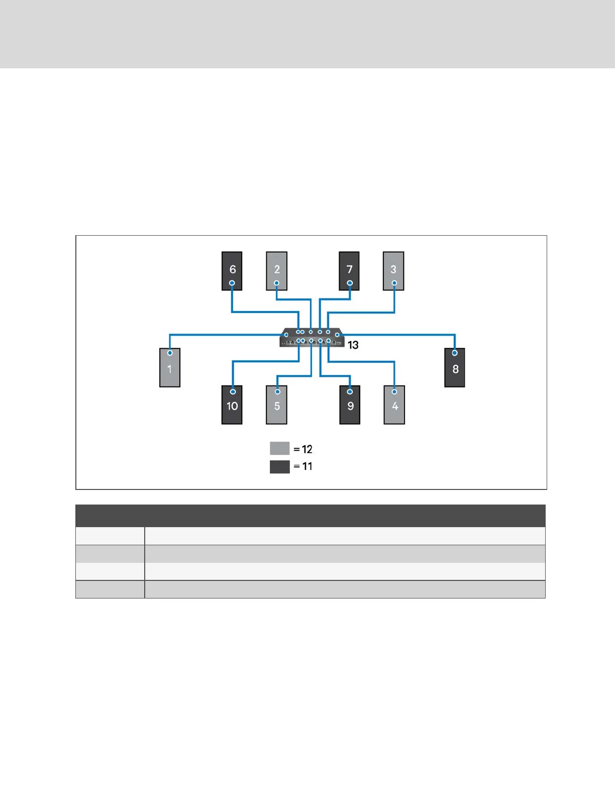
Figure 5.1 Example Layout Standby/Operating Unit Address Assignment
Item Description
1 to 10 Assigned address of the thermal-management unit.
11 Operating units.
12 Units on standby.
13 Network switch.
Vertiv™ | Liebert® iCOM™Installer/User Guide
58
 Loading...