™
Page 29 of 81
4 Using the vLoc3-Pro
4.8 Depth & Current Measurement
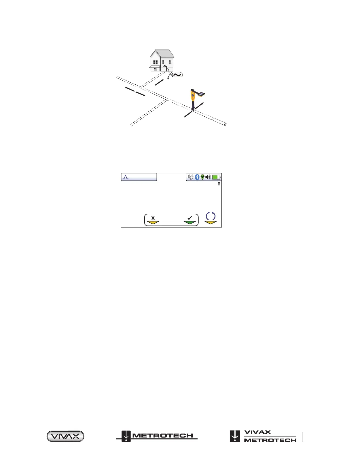
If the depth measurement feature is activated, it is possible to take depth measurement estimations. To take a depth
measurement, rst pinpoint the position of the line as above. Place the tip of the vLoc3-Pro on the ground making sure it is
vertical and across the line i.e. the compass indicating Forward/Back. Momentarily press the “i” button. The screen will change
to a screen similar to the one below.
Log 2
0.54m 163mA
50°42′59.90570′′N
3°26′35.54358′′W
27.50m
0
SD
Note that if Omni mode is selected the orientation of the locator is not important but it is still necessary to pinpoint the line
accurately before taking a depth measurement.
The signal current value will also be displayed. This feature is useful for conrming that the detected signal is radiating from
the correct line. In the event the signal is “bleeding o” onto other services, these signals will generally be less than that of the
originating signal. However, care should be taken as the signal current will gradually reduce over the length of the line, but
watching for a sudden drop in current over distance should indicate that either:
1. There is a ground fault on the line which is shunting signal to ground.
2. There is a “T” o from the mainline.
3. The operator has migrated from the connected line to a line which has some signal that has bled across from the main line.
4.9 Distorted Fields
When locating, always be aware that you are locating the signals radiating from the buried line, these radiated elds, as they are
called, can be distorted by other lines or electromagnetic signals from buried lines or metallic features like crash barriers or wire
mesh fences.
As seen previously, the vLoc3-Pro has the ability to detect the presence of possible distortion i.e. the Vector screen has a circle
drawn around the target line which increases in size in the presence of possible distortion, and the Plan view screen has “Tram”
lines either side of the calculated position which move further from the line as more possible distortion is detected. However,
when using the traditional screen, the risk of an inaccurate location can be reduced further by the following:
● Check to see if the signal is being distorted by other radiated fields. Locate the cable, first in the “Peak” mode, and then in
the “Null” mode (or use the left/righty arrows). The two locations should indicate that the cable is in the same place. If they
do not, the signal field is distorted, and the depth and current measurement may be inaccurate.
 Loading...