™
Page 63 of 81
7 Loc3-5Tx Transmitter
7.4 Frequencies
7.4.1 Frequencies and Power Output
The Loc3-5Tx transmitter is supplied with a predened set of transmit frequencies. The most commonly used frequencies are
preset by the factory. Additional frequencies can be added from the frequency select list. (See section 1.4.2 for access to this
menu).
Example of standard frequencies/preset at the factory are:
● 512Hz (where electrical systems are 60Hz) direct connection – 5 watts.
● 640Hz (where electrical systems are 50Hz) direct connection – 5 watts.
● 8 kHz direct connection – 5 watt.
● 33 kHz direct connection – 5watt.
● 65 kHz direct connection – 1 watt.
● 83.1 kHz, 131 kHz direct connection – 1 watt (depending on region).
● 200 kHz direct connection – 1 watt (depending on region).
● Some other frequencies with 5Watt output:
ο Direction connection: 256Hz, 491Hz, 982Hz, etc.
ο Direct and clamp connection: 8.19 kHz, 8.44 kHz, 9.5 kHz, 9.82 kHz, 32.8 kHz, 38 kHz.
● Some other frequencies with 1W output: 89 kHz, 131 kHz, 200 kHz.
● Clamp connection: any frequency from 8 kHz up to the highest allowed frequency (depending on region).
● Induction Frequency: this transmitter is a broad-band induction unit. It means that user can select for the induction mode any
frequency he wants, from 8 kHz up. (highest available frequency depends on region) NOTE: see section 1.4.2 for frequency
activation procedure.
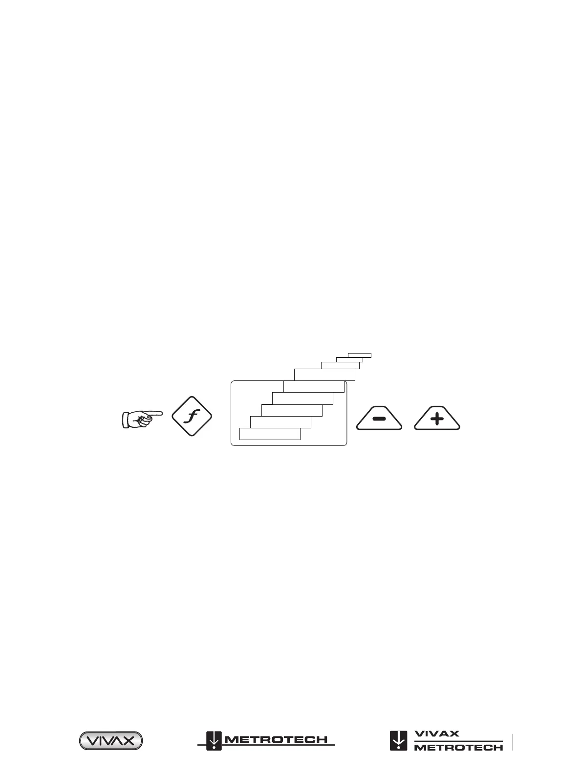
200kHz
131kHz
83.1kHz
65.5kHz
32.8kHz
8.19kHz
Pushbutton Pushbutton
As with most manufacturers the clamps and induction antennas are tuned to specic frequencies, and do not work over the
complete range of frequencies.
Frequencies are selected by pressing the “f” pushbutton which toggles through the available frequencies for the selection mode.
The frequency is automatically selected if you don’t toggle past it within two seconds. The frequency is shown on the display.
NOTE:
The output current is shown in large characters on the display – to increase or reduce the power output press “+” or “-”. The
vertical bar graph at the bottom of the display indicates which of the ve current output steps is being used. If the transmitter can
supply the requested current, the bar will turn black. If the bar does not turn black, improving the ground connections or wetting
the ground where the earth stake in positioned, may help. However, it may not be able to achieve the current setting requested
because the impedance of the line is too high for this setting. If this happens it is best to select a setting that has a black bar, this
will ensure a stable output.
The current being transmitted will be limited by the impedance of the cable, therefore it is not unusual to increase the output
level, but see no increase in the current displayed. This is not a fault with the transmitter.
The transmitter will always revert to rst level output when switched on – this is a power saving feature – in most circumstances
this output level is sufficient. Increasing the output power unnecessarily will reduce the battery life unnecessarily. All other
settings remain the same as the last setting used.
 Loading...