October 2012
3-43
ColorQube 8570/8870 Service Manual
Image Specifications
Image Quality
Xerox Internal Use Only - Revised, 3rd Revision
NOTE: To derive the skew specification for a particular media size, measure the width of the
leading edge in millimeters. Next, divide the measured length by 1000, then multiply by the
appropriate Image Area Tolerance specification in milli-radians. For example, A 5 in. by 7 in.
custom page would have a leading edge width, in millimeters, of 127 mm (5 in.). Dividing the
127 by 1000 (127/1000), then multiplying the result by the 11 milli-radians specification results
in a maximum skew of 1.4 mm (127/1000) x 11 = 1.4 mm.
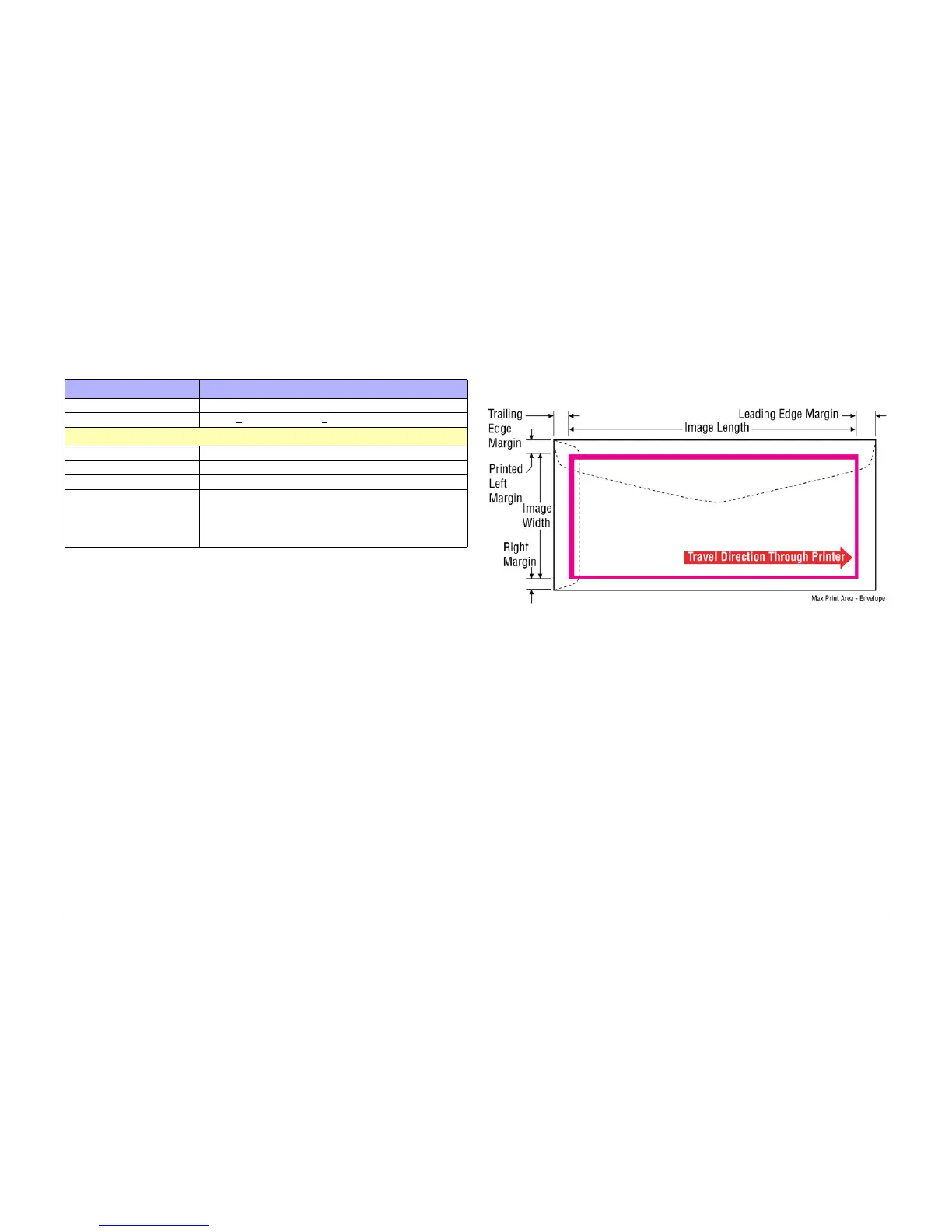
Maximum Print Area - Envelope
Maximum Print Area
• Lead Edge Margins: 0.5 mm
• Trail Edge Margins: 0.5 mm
• Right/Left Margins: 0.5 mm
The listed envelopes have Right/Left Margins at 0.15 mm.
• #10 Envelope, DL Envelope, C5 Envelope, #6 3/4 Envelope, and 6 x 9 Envelope
Figure 3 Maximum Print Area - Envelope
Table 2 Printer Skew Specifications
Characteristic Specification
Printed Left Side Margin 5.0 mm + 2.0 mm (0.197 in. + .080 in.)
Leading Edge Margin 5.0 mm + 1.3 mm (0.197 in. + .050 in.)
Image Area Tolerance Zone
Image Skew, Envelopes 11.5 milli-radians max across the width of the leading edge.
Image Skew, 3x5 Card 14.0 milli-radians max across the width of the leading edge.
Image Skew, All other sizes 7.0 milli-radians max across the width of the leading edge.
Resolution/ Gradation • Fast Color: 225 x 400 dpi
• Standard: 300 x 450 dpi
• Enhanced: 525 x 450 dpi
• Photo: 525 x 2400 dpi
 Loading...