108
5.8 Encoder ABZ phase frequency division output
The servo driver outputs the differential signal through the frequency division output circuit. It can
provide position signal for the control of the upper computer or pulse signal for the driven servo, so as
to realize the follow-up control of the master-slave shaft.
1. Encoder frequency division output specification
Hardware version 3131 and
earlier [CN1]
Hardware version 3131 and
later [CN0]
A phase frequency
division output
B phase frequency
division output
Z phase frequency
division output
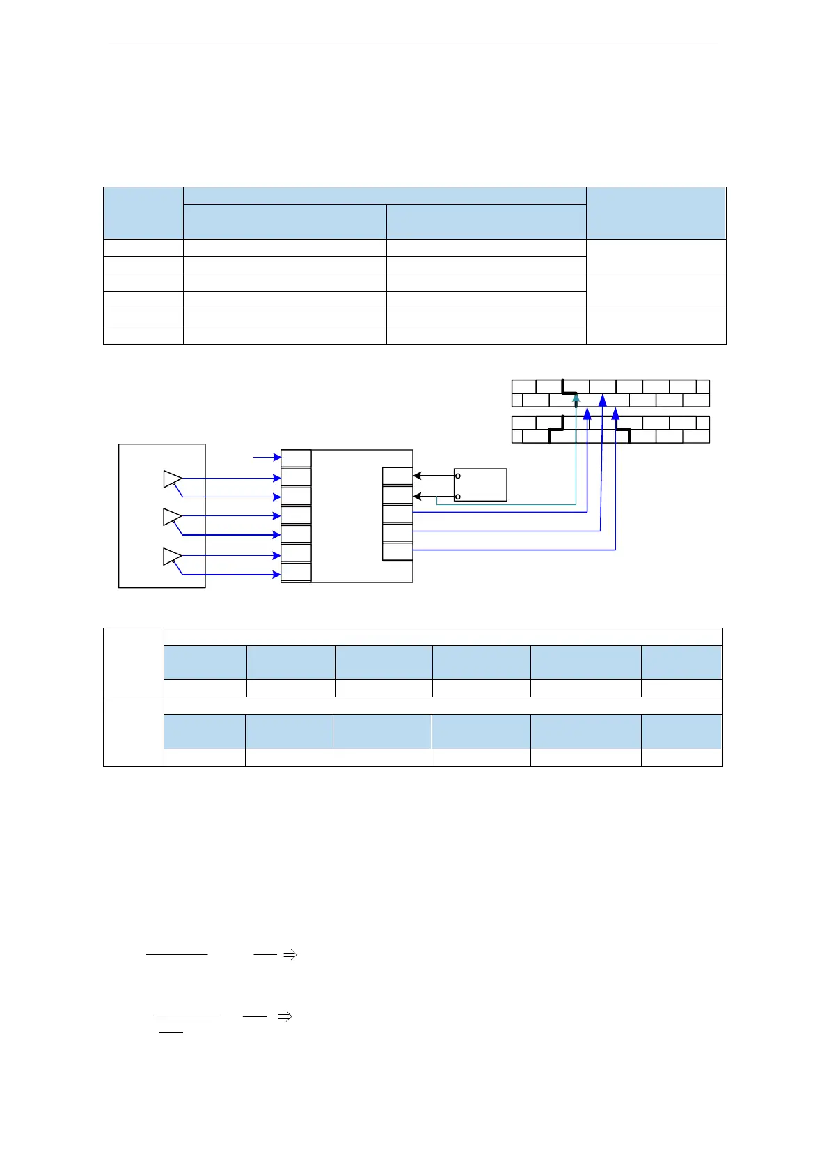
2. Wiring diagram
JS-IDC-ABZ
GND
A+
A-
B+
B-
Z+
Z-
COM
A
B
Z
24V
Input Output
Switch
power
supply
N COM X1 X3 X5 X7
L FG X0 X2 X4 X6
0V Y0 Y2
COM1
Y5 Y7
24V
COM0
Y1 Y3 Y4 Y6
AO+
AO-
BO+
BO-
ZO+
ZO-
3. Encoder feedback pulse number per turn
Set the number of feedback pulses per turn of encoder (low-order position)
Set the number of feedback pulses per turn of encoder (high-order position)
Note:
(1) Output pulses per turn: P0-19 * 10000 + P0-18. It can be any positive integer.
(2) Encoder feedback will be output from CN0 port (hardware version 3131 and earlier encoder
feedback output at CN1 port). It is recommended that the lower computer accept pulse with AB phase
counter.
If AB phase counting is adopted, the counting value of motor rotation for one turn is 4 times of the
set pulse number per turn of encoder (P0-18 + P0-19 * 10000).
(3) The pulse output frequency of each phase shall not exceed 1MHz, and the number of pulses per
cycle can be set in cooperation with the z-phase pulse estimation formula.
Example: Assume the actual speed of motor is 3000rpm,
28.8 1
3000×ppr 10
×2 ≥
6
ppr ≤ 18720
, then
the setting of pulse number feedback per turn shall not exceed 18720.
1 1
× ppr 10
≥
6
ppr ≤ 20000
n
60
, then
the setting of pulse number feedback per turn shall not exceed 20000.
(4) Assuming that the number of feedback pulses per turn is 10, the output signals of phase A (PAO)
 Loading...

