48
F1-05 = 0: cancel enable, enter bb status.
F1-05 = 1: forced enable, servo is in RUN status.
Note:
(1) After power on again, the forced enable set by F1-05 will fail.
(2) If it needs to enable when power on and still enable after re-power on, P0-03 should be set to 1
and P5-20 to n.0010.
7. Reset turns of absolute encoder (F1-06)
Refer to chapter 5.7.5.
4.5 Fault alarm handling
When a fault occurs, the alarm status is automatically jumped out, and the alarm number is
displayed. When there is no fault, the alarm status is invisible. In the alarm state, the fault can be reset
by writing 1 to F0-00 through panel operation.
If the servo power supply OFF makes the servo alarm, it is not necessary to clear the alarm.
Note: When an alarm occurs, the cause of the alarm should be eliminated first, and then the alarm
should be removed.
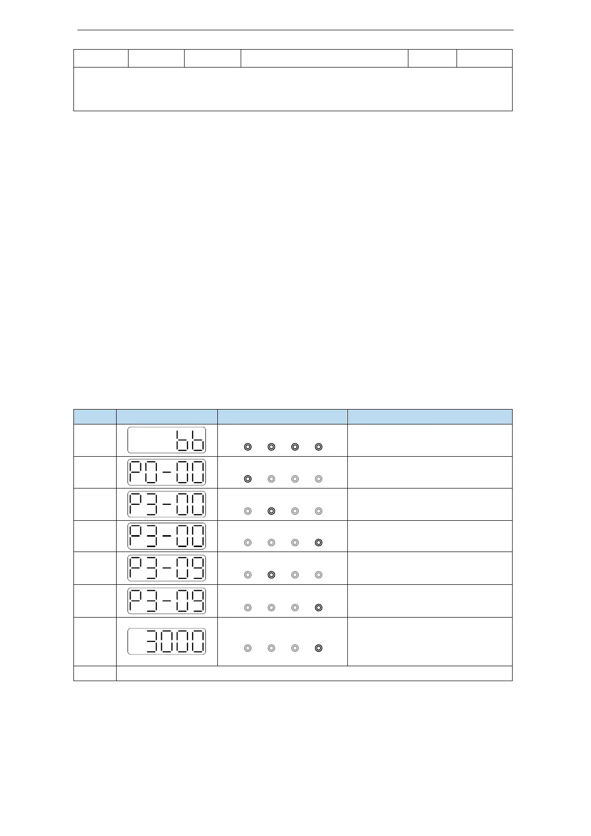
4.6 Parameter setting example
An example is given to illustrate the operation steps when the content of parameter P3-09 is changed
from 2000 to 3000.
Press INC for three times to show
P3-00
Press ENTER, the last 0 will flash
Long press ENTER to show the
value of P3-09
Press INC, DEC, ENTER to
increase decrease or shift, after
changing, long press ENTER to
confirm
Note: When the setting parameter exceeds the range that can be set, the driver will not accept the
setting value, and the driver will report E-021 (parameter setting exceeds the limit). The parameter
setting overrange usually occurs when the upper computer writes parameters to the driver through
communication.
 Loading...

