70
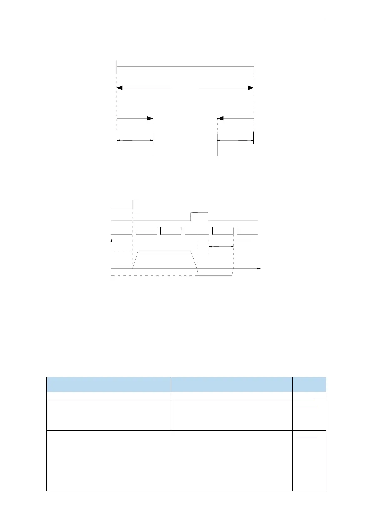
Find reference origin diagram:
Sequential diagram of finding reference origin on forward side:
Steps:
(1) Install limit switch at forward and reverse side. At the rising edge of /SPD-A, motor runs forward at
the speed of P4-01 to find the reference origin on forward side.
(2) After the working table hit the limit switch, the motor stop as the mode set by parameter P0-28
(3) Motor leaves the limit switch at the speed of P4-02. After the working table left the limit switch, the
motor run at the Z phase signal position of No.n optical encoder. This position is considered as the
coordinates origin, n is decided by parameter P4-00.
5.3.2 Position control (external pulse command)
P0-01 control mode selection
Set to 6: external pulse mode
P0-10 pulse instruction form
P0-11 Motor pulse numbers per rotation*1
P0-12 Motor pulse numbers per
rotation*10000
P0-13 Electronic gear ratio (numerator)
P0-14 Electronic gear ratio (denominator)
P0-92~P0-93 32-bit electronic gear ratio
(numerator)
P0-94~P0-95 32-bit electronic gear ratio
Setting of command pulse number required
for one revolution of motor
P0-11 and P0-12=0, P0-13/P0-14 are
effective
P0-11~P0-14 are 0, P0-92~P0-95 are
valid
32-bit electronic gear ratio (numerator):
P0-92*1 + P0-93 *10000
Reference origin
of forward side
Reference origin
of reverse side
 Loading...

