71
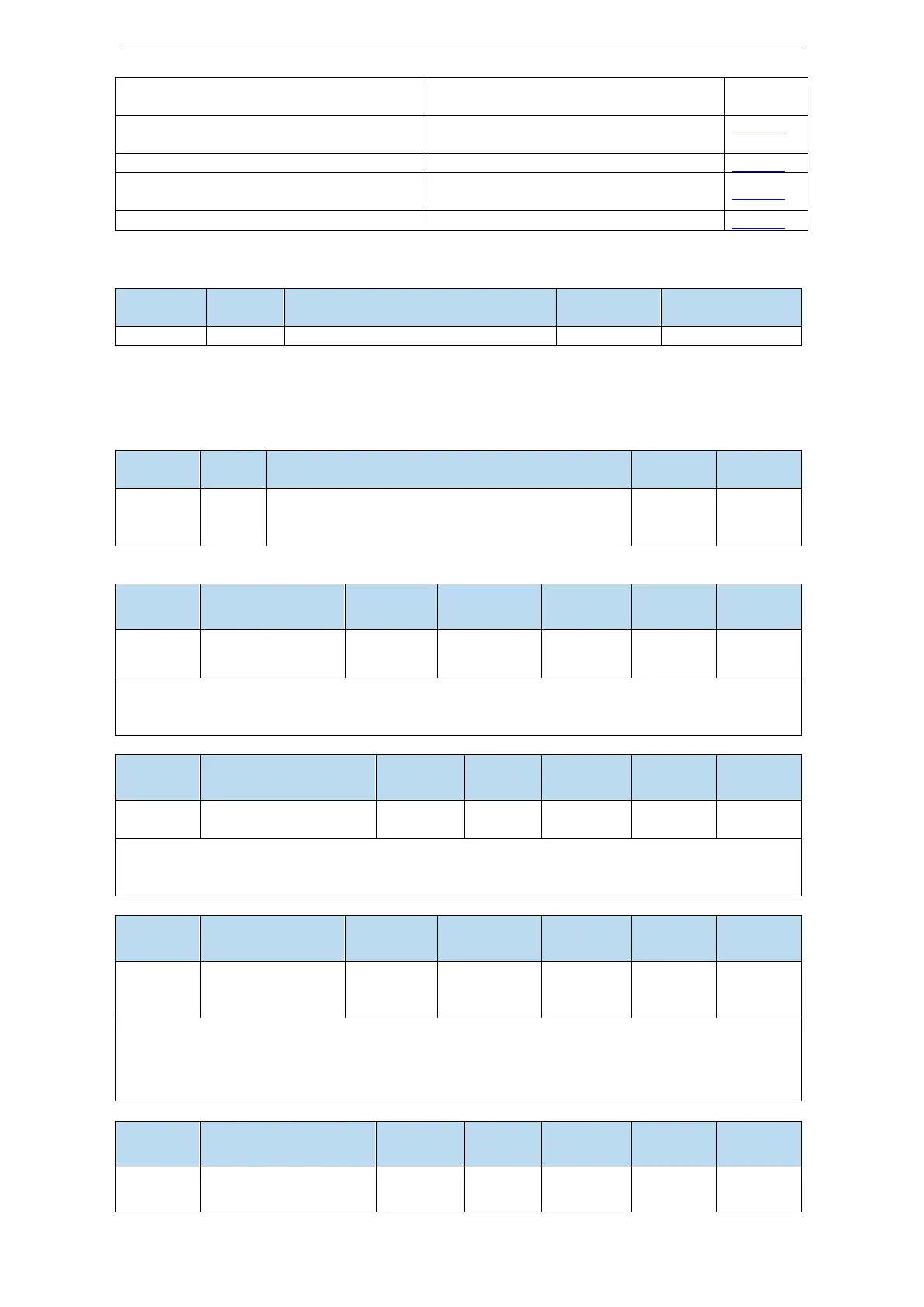
32-bit electronic gear ratio denominator:
P0-94*1 + P0-95 *10000
P0-09 Pulse command setting
You can set the command direction and
filter time of low-speed pulse respectively
Full closed loop input related configuration
P0-88 high speed pulse mode selection
P0-89 high speed pulse command filter time
5.3.2.1 External pulse position mode
Control the position by external pulse
5.3.2.2 Forward direction of pulse instruction and pulse form
1. Pulse input channel switching
High/low speed pulse command input mode switch:
0: normal pulse command input mode;
1: High speed pulse command input mode.
2. set the forward direction of pulse instruction
forward direction
of pulse instruction
P0-09 will change the counting direction of the internal counter in the servo system. The counting
direction determines the rotation direction of the motor. Therefore, this parameter can be adjusted if
the actual rotation direction of the motor is different from the expected direction in the position mode.
Low speed pulse
command filter time
P0-09.2 is pulse filter time. It can enhance the anti-interference ability of low-speed pulses (less than
200K). When the input is less than 700K, the maximum filtering time F is recommended. When the
input pulse frequency exceeds 1M, the filtering time should not be more than 7.
Predistribution of
input pulse
command filter
P0-09.3 setting value is n (range is 0~7), the received pulse number is 2^-n of normal one. The
received frequency is 2^-n of original one.
For example, pulse number per rotation is 10000, sending frequency is 10KHz, pulse number is
10000, when P0-09=1000, then U0-12=5000, U0-00 is 2^-n of original one.
High speed pulse
command filter time
 Loading...

