Page 16 FTDX9000D OPERATION MANUAL
INSTALLATION AND INTERCONNECTIONS
COMMON
COMMON
DOT
DOT
DASH
DASH
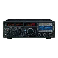
Key, Keyer, and Computer-Driven Keying Interconnections
The FT DX 9000 includes a host of features for the CW operator, the functions of which will be detailed in the “Operation”
section later. Besides the built-in Electronic Keyer, two key jacks are provided, one each on the front and rear panels, for
convenient connection to keying devices.
The Menu selections below, allow you to configure the front ane rear panel KEY jacks according to the device you wish to
connect. For example, you may connect your keyer paddle to the front panel KEY jack, and use Menu #41 for paddle input,
while connecting the rear panel’s KEY jack to the keying line from your personal computer (which emulates a “straight
key” for connection purposes), and configure the rear panel jack using Menu #43.
Both KEY jacks on the FT DX 9000 utilize “Positive” keying voltage. Key-up voltage is approximately +5V DC, and key-
down current is approximately 1 mA.
Advice
When connecting a key or other device to the KEY jacks, use only a 3-pin (“stereo”) 1/4” phone plug; a 2-pin plug will
place a short between the ring and (grounded) shaft of the plug, resulting in a constant “key-down” condition in some
circumstances.
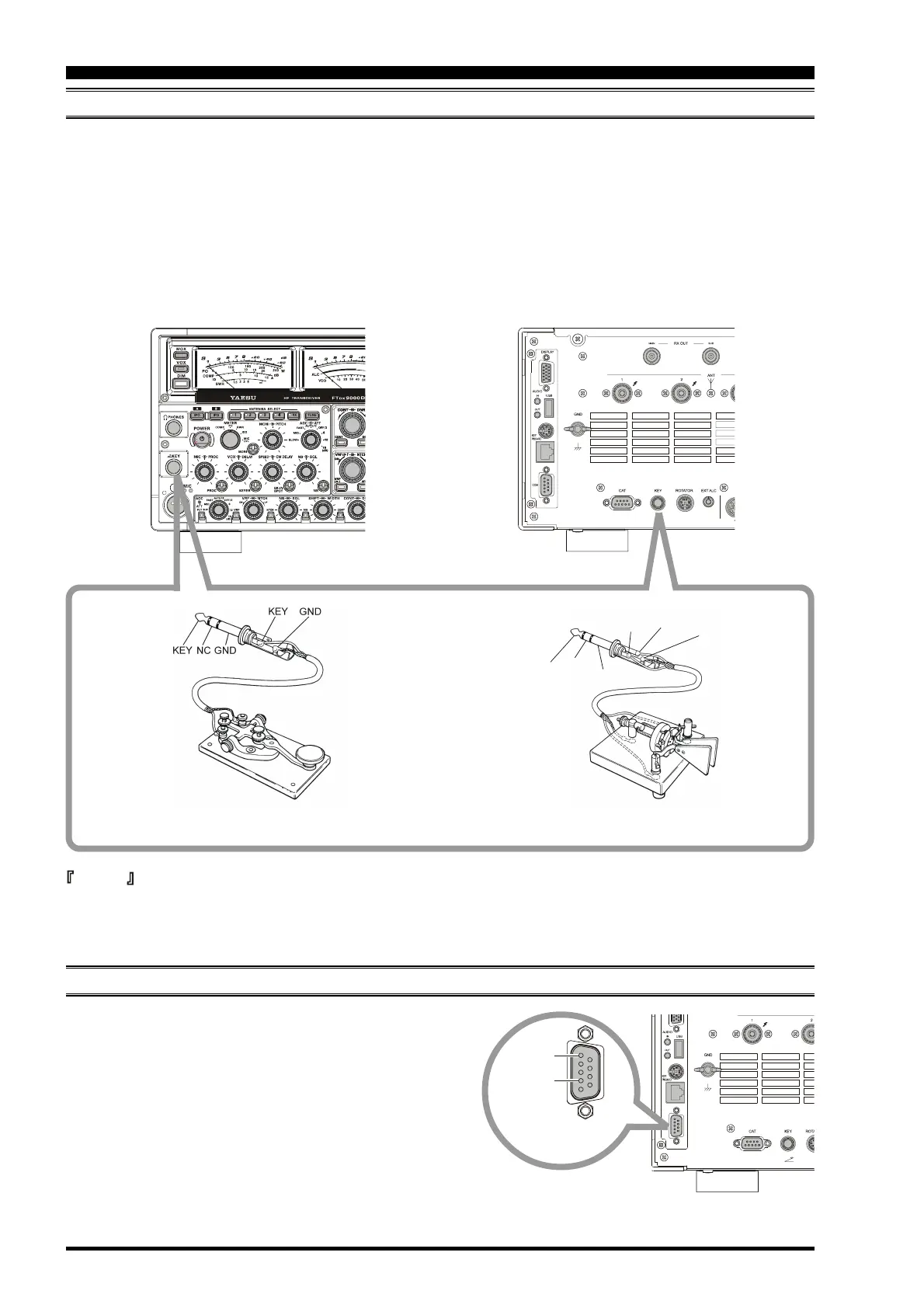
Pin 2
GPS DATA IN
Pin 5
GND
CONNECTING A GPS RECEIVER
If you connect a properly-equipped after-market GPS re-
ceiver (not supplied) to the COM port on the back of the
transceiver, the "Rotator" page on the TFT display will au-
tomatically include a Great Circle map centered on your
location.
Connect a GPS receiver capable of output of NMEA-0183
data to the COM port. The data line connects to Pin 2, and
the ground shield connects to Pin 5.
This transceiver can support the GGA, GLL, and RMC Data
Sentences from the GPS unit.
 Loading...


