Page 39FTDX9000D OPERATION MANUAL
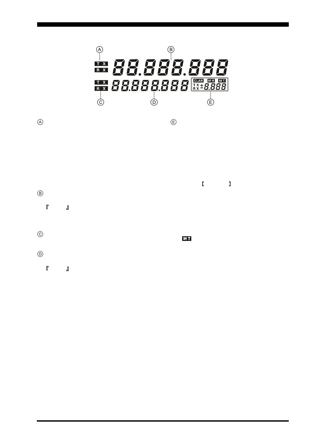
Main (VFO-A) Band TX/RX Indicators
These combination lamp-buttons select and indicate the
transmit/receive status of the Main (VFO-A) band. When
the green “RX” lamp is lit, the receiving frequency is
under control of the main knob and display (either VFO-
A or a recalled memory channel). When the red “TX”
lamp is lit, the transmitting frequency is under control
of the main knob and display. Thus, for “normal” (non-
split) operation, both the red and green lamps associ-
ated with the main tuning knob will be illuminated.
Main (VFO-A) Frequency Display
This is the Main (VFO-A) band frequency display.
Advice
When setting the CTCSS frequency for Encoding or
Tone Squelch operation, the tone information will
appear in this area during setup.
Sub (VFO-B) Band TX/RX Indicators
These combination lamp-buttons select and indicate
the transmit/receive status of the Sub (VFO-B) band.
Sub (VFO-B) Band Frequency Display
This is the Sub (VFO-B) band frequency display.
Advice
The Tone Encoder/Decoder frequency is indicated
during the setup process.
Multi-Panel
This field within the frequency display area provides
several indications, depending on the frequency con-
trol mode in use:
CLAR (Clarifier)
This window displays the Clarifier frequency offset
from the Main (VFO-A) band frequency. The Clari-
fier is engaged when the CLAR LED is illuminated.
MR (Memory Recall)
When the MCH/GRP switch is pushed, the cur-
rently-selected Memory channel or Memory Group
number will be displayed in this window.
MT (Memory Tune)
If you rotate the Main Tuning Dial (or change the
mode) during memory operation, the transceiver will
change into the “Memory tune” mode to indicate that
the memory contents have been temporarily changed;
“ ” lights up to confirm this change.
Repeater Shift Data
During FM operation, the Repeater Shift will be indi-
cated in this window.
A Negative frequency shift will be indicated by “-”
while a Positive frequency shift will be indicated by
“+” in the window. During Simplex operation (no
shift), “S” will be displayed.
FREQUENCY DISPLAY
 Loading...


