Page 63FTDX9000D OPERATION MANUAL
RF GAIN (SSB/CW/AM MODES)
The RF Gain controls provide manual adjustment of the gain levels for the receiver RF and IF stages, to account for noise
and/or signal strength conditions at the moment.
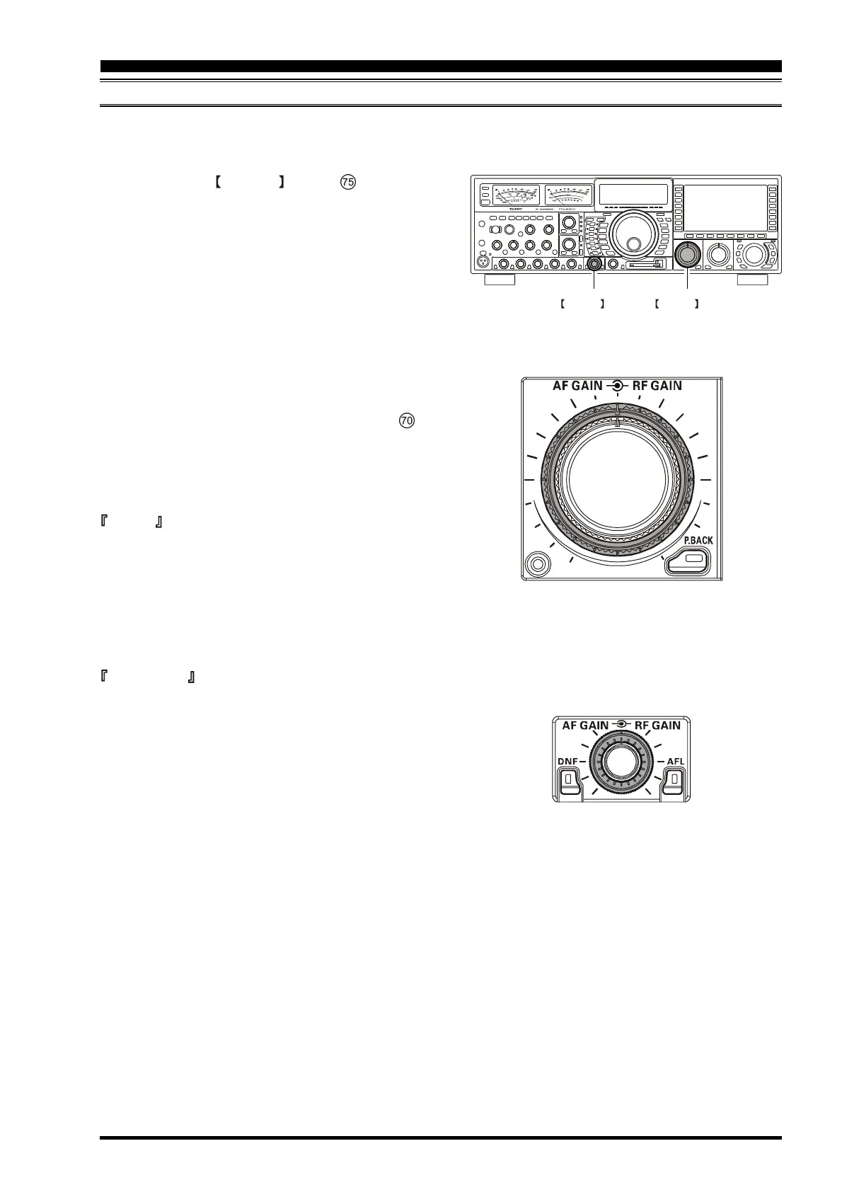
Main (VFO-A) RF Gain Adjustment
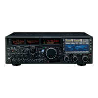
The Main (VFO-A) RF GAIN control # shoud, ini-
tially, be rotated to the fully clockwise position. tjhis is the
point of maximum sensitivity, and counter-clockwise ro-
tation will gradually reduce the system gain.
H As the RF Gain control is rotated counterclockwise to
reduce the gain, the S-meter reading will rise. this in-
dicates that the AGC voltage being applied to the re-
ceiver (to reduce the gain) is increasing.
H Rotating the RF Gain control to the fully counter-clock-
wise position will essentially disable the receiver, as
the gain will be greatly reduced. In this case, as well,
the S-meter will appear to be “pegged” against the right
edge of the analog S-meter scale.
H The sub (VFO-B) receiver’s RF Gain control (# )
operates identically to the Main (VFO-A) band RF Gain
control. The effects of counter-clockwise rotation of
the Sub receiver's RF Gain control may be observed
visually on the Sub (VFO-B) band S-meter.
Advice
Reception frequently can be optimized by rotating the RF
Gain control slightly counter-clockwise to the point where
the incoming noise level is just about the same as the “sta-
tionary” meter needle position as set by the adjustment of
the RF Gain control. This setting ensures that excessive
gain is not being utilized, without so much gain reduction
that incoming signals cannot be heard.
Quick Point
The RF Gain control, along with the IPO and Attenuator
features, all affect the system receiver gain in different
ways. As a first step in dealing with high noise or a crowded,
high-level signal environment, the IPO generally should
be the first feature engaged, if the frequency is low enough
to allow the preamplifier to be bypassed. Thereafter, the
RF Gain and Attenuator features may be employed to pro-
vide precise, delicate adjustment of the receiver gain so as
to optimize performance fully.
SUB(VFO-B)
RF GAIN Knob
MAIN(VFO-A)
RF GAIN Knob
MAIN (VFO-A)
SUB (VFO-B)
CONVENIENT FEATURES
 Loading...


