EasyManua.ls Logo

Yaesu FTDX9000D User Manual

Yaesu FTDX9000D
156 pages
To Next Page IconTo Next Page
To Previous Page IconTo Previous Page
Page #66 background imageLoading...
Page #66 background image
Page 64 FTDX9000D OPERATION MANUAL
USING THE µ-TUNE FEATURE
The µ-Tune system is an advanced preselector for the RF front end of the Main (VFO-A) receiver, providing a much narrower
passband than the VRF circuit. The Q of the µ-Tune filter is so tight as to provide significant suppression of signals little more than
10 kHz away from your current operating frequency, and manual adjustment of the µ-Tune filter's center frequency allows you to
position the shoulder of the filter in such a way as to enhance interference rejection to one side or another of your current frequency.
Because the insertion loss of the µ-Tune is somewhat higher than that of the VRF, we have also provided the capability to disengage
µ-Tune, and engage VRF, should your antenna and noise environment lead to system noise figure concerns when using µ-Tune.
The FT DX 9000D’s Main (VFO-A) band receiver is equipped with µ-Tune modules covering the 1.8 ~ 14 MHz Amateur
bands. On the 18 ~ 50 MHz bands on the Main (VFO-A) receiver, and on all bands on the Sub (VFO-B) side, the VRF
circuit is provided.
µ-Tune Operation on the Main (VFO-A) Receiver
1. Press the VRF/µ-T switch (# ). The imbedded
Red LED will light up.
H The µ-Tune circuit will automatically align itself
onto your operating frequency.
H Remember that µ-Tune only operates on the Main
(VFO-A) band on the 14 MHz and lower bands.
2. Now rotate the VRF/µ-T knob to peak the response
(background noise) or reduce interference.
H A pictorial representation of the tuning position
of the µ-Tune filter will appear on the bar graph
on the TFT.
H The amount of change in the center frequency of
the µ-Tune filter, when rotating the VRF/µ-T
knob by one click, can be configured using Menu
item “GENERAL 035 µTUNE DIAL STEP.”
H If you have performed manual adjustment of the
µ-Tune filters center frequency, you may press
and hold in the VRF/µ-T key for two seconds
to re-center the filter response on your current op-
erating frequency.
3. Press the VRF/µ-T switch (momentarily) once more
to disengage the µ-Tune filter; the imbedded Red LED
will switch off. In this mode, only the fixed bandpass
filter for the current band will be engaged.
MAIN(VFO-A)
VRF/µ-T switch
MAIN(VFO-A)
VRF/µ-T knob
MAIN (VFO-A)
µ-Tune filter will appear
on the bar graph
µ-Tune filter will appear
on the bar graph
Quick Note
The permeability-tuning concept utilized in the µ-Tune cir-
cuit dates back many decades, as it was incorporated in such
classic transceivers as the FT-101 and FT-901 series, in ad-
dition to the FT DX 400 and similar models. The µ-Tune
circuit in the FT DX 9000 is the highest development of this
circuit concept ever employed in an Amateur transceiver.
Advice
H The µ-Tune filters are the most advanced, selective RF preselector filters ever incorporated into an Amateur Radio
transceiver. The RF selectivity provided by µ-Tune can be of tremendous value in ensuring quiet, intermod-free recep-
tion even in the most crowded bands on a contest weekend. The µ-Tune filters provide RF selectivity on the order of a
few dozen kHz at -6 dB, at the expense of a few dB of system gain on bands where noise figure is seldom an issue. You
will notice that the S-meter deflection, when µ-Tune is engaged, is slightly less than when it is out of the circuit; this is
normal. If your antenna system gain is so low as to make it impossible to hear band noise when µ-Tune is engaged
(highly unlikely), just switch it out or revert to the VRF system, which has slightly less insertion loss.
H As you tune around on an amateur band with µ-Tune engaged, the microprocessor automatically commands the stepper
motor driving the toroid core stack to center the filter on your current operating frequency (the tuning resolution is 5
kHz). You may, however, use the VRF/µ-T knob (# ) to skew the filter response to one side or the other from your
operating frequency, to deal with heavy interference on one side. To re-center the µ-Tune filter on your operating
frequency, and eliminate any offset, press and hold in the VRF/µ-T switch (# ) for two seconds.
H A pictorial representation of the tuning position of the µ-Tune filter will appear on the bar graph on the TFT.
H While µ-Tune is a superior RF preselection circuit, it may be disabled via the Menu; if this is done, the VRF circuit will
engage when the VRF/µ-T switch is pressed. To disble µ-Tune, go to Menu item “GENERAL 035 µTUNE DIAL
STEP” and set the selection to “OFF.”
The FT DX 9000D includes an unmatched array of RF selectivity-enhancing features. Please study the material below
carefully, so as to understand the various features complete.
Advanced Interference-Suppression Features: RF Front End

Table of Contents

Question and Answer IconNeed help?

Do you have a question about the Yaesu FTDX9000D and is the answer not in the manual?

Yaesu FTDX9000D Specifications

General IconGeneral
BrandYaesu
ModelFTDX9000D
CategoryTransceiver
LanguageEnglish

Summary

Getting Started: Before You Begin

Connecting AC Power

Instructions for connecting AC power, including details on front and rear power switches.

Setting Your Local Time

Importance of setting the local time for correct function of several features.

Configuring Your FT DX 9000 Using the Menu

Guide on how to change transceiver settings using the menu system and saving changes.

Connecting and Selecting the Microphone

Instructions on connecting and selecting front panel XLR or rear panel 8-pin microphone connectors.

Adjusting Main Dial Torque and Power

Procedure for adjusting the main dial torque and restarting power after fluctuations.

Resetting the Microprocessor

Procedures for resetting memories, menu settings, or performing a full reset of the transceiver.

FTDX9000 Features Overview

Panel Layout and Display Features

Description of the front panel layout, VFD display, LEDs, and tuning dial for visibility and ease of use.

Advanced Receiver Technologies

Details on DSP, µ-Tuning filters, VRF, Roofing filters, and Contour filter for enhanced reception.

Receiver Performance Features

Information on Sloped AGC, AF Limiter, Adjacent Channel Monitor, and receiver front-end design.

Transmitter and Audio Features

Description of the final amplifier design, Class-A operation, and parametric microphone equalizer.

Accessories and Options

Supplied Accessories

Lists accessories supplied with the transceiver, including FH-2, CF Card, and cables.

Available Options

Lists available optional accessories for the transceiver, such as microphones and headphones.

Installation and Interconnections Guide

Antenna and Coaxial Cable Considerations

Guidance on selecting antennas, coaxial cable quality, and impedance matching.

Grounding System Requirements

Importance and methods for establishing an effective ground system for safety and performance.

Connecting Antennas and Power Cables

Illustration and instructions for connecting antenna coaxial and AC power cables correctly.

Connecting Peripherals: Microphone, Headphones, FH-2

Details on connecting microphones, headphones, and the FH-2 remote control keypad.

Keying Device and GPS Receiver Connections

Information on connecting CW keying devices, computer interfaces, and GPS receivers.

Linear Amplifier and External Device Interfacing

Guide for connecting the VL-1000 linear amplifier and interfacing with other linear amplifiers.

Front Panel Controls Explained

Core Operation Switches: MOX, VOX, DIM, PHONES, POWER

Explanation of the MOX, VOX, DIM switches, PHONES jack, and POWER switch functions.

Keying, Microphone, and Tuning Controls

Details on KEY jack, XLR microphone connector, IPO switch, Antenna Select, and TUNE switch.

Meter, Monitor, and Filter Control Knobs

Explanation of METER, MONI switches, and associated knobs for AGC and attenuation.

Processor, Delay, Keyer, and Noise Reduction Controls

Controls for Speech Processor, VOX delay, CW Keyer, Noise Blanker, and Squelch.

VRF, µ-TUNE, and Notch Filter Controls

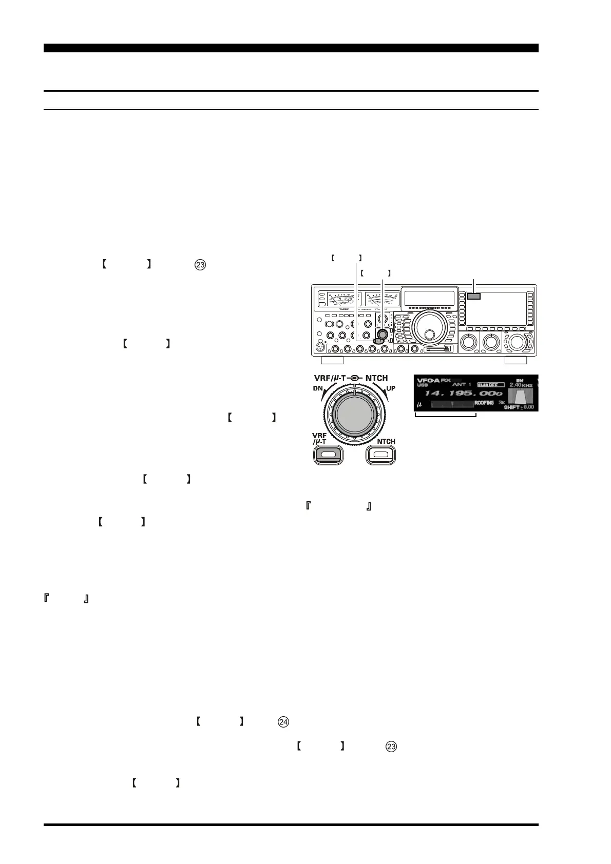
Switches and knobs for VRF, µ-TUNE, and IF Notch filters for interference rejection.

Bandwidth, Contour, and Noise Reduction Adjustments

Controls for IF bandwidth, Contour filter, Digital Noise Reduction, and Digital Notch Filter.

VFO/Memory and Band Selection Controls

Buttons for VFO/Memory modes, band selection, and indicators like BUSY and SPLIT.

Frequency Display and Indicator Functions

Explanation of frequency displays, TX/RX indicators, S-meters, and status indicators.

Sub Band (VFO-B) Receiver Controls

Switches and knobs for Sub band receiver functions like Roofing, AGC, VRF, and Notch filters.

Sub Band (VFO-B) DSP and Noise Reduction Controls

Controls for Sub band DSP filters (Shape, Slope, Narrow) and noise reduction.

Transmit Power, Bias, and Class-A Operation Controls

Controls for RF Power, BIAS adjustment, and engaging Class-A transmission mode.

CF Card Slot and AF/RF Gain Control Functions

Details on the CF card slot and adjustment of AF/RF GAIN controls.

Audio Processing and Transmission Feature Controls

Controls for P.BACK (audio playback), AFL, SHIFT/WIDTH, ACM, and Clarifier functions.

Frequency Navigation and Band Selection Features

Using the CLAR/VFO-B knob for frequency tuning, band selection, and mode selection.

Frequency Entry and Offset Controls

Using FAST/RX, BAND/MHz/TX, B-MODE/CLEAR, and A/B switches for frequency management.

Rear Panel Connections and Features

Antenna and Receiver Connections

Description of ANT, RX OUT, and RX ANT jacks for antenna and signal routing.

Power, Audio, and Control Interfaces

Details on power switch, AC IN, MIC jack, and REMOTE connector for external control.

Data, Transverter, and Amplifier Interfaces

Connectors for +13.8V, PTT, PATCH, EXT SPKR, AF OUT, RTTY, PACKET, TRV, ACC, TXGND, BAND DATA, and EXT ALC.

External Device and Computer Interfaces

Connectors for KEY, CAT, GND, COM, KEY BOARD, AUDIO OUT/IN, DISPLAY, and USB.

Frequency Display and TFT Features

Band and TX/RX Status Indicators

Indicators for Main and Sub band transmit/receive status.

Frequency Display Fields

Main and Sub band frequency display fields, showing operating frequency and status.

Multi-Panel Display Functions

Indications for CLAR, Memory Recall (MR), Memory Tune (MT), Repeater Shift, and frequency control mode.

TFT Feature and Control Details

Amateur Band and Frequency Entry Keys

Keys for band selection, 50 MHz access, TRV control, and General Coverage VFO.

Direct Frequency Entry and Menu System

Engaging direct frequency entry and accessing the Menu system for configuration.

TFT Function Keys

Explains the use of 'Function' keys associated with each TFT page for operational capability.

Basic Operation: Receiving

Initial Power-Up and Frequency Setup

Steps for powering on the transceiver, initial boot-up, and setting AF GAIN and MAIN RX.

Dual Receive and Band Selection

Engaging the Sub RX switch for Dual Receive and selecting operating bands.

Antenna and Mode Selection Procedures

Selecting antennas using ANTENNA SELECT switches and operating modes using MODE keys.

Squelch and Tuning Dial Operations

Adjusting the SQL control and using the main tuning dial for band operation.

Clarifier Operation on Main (VFO-A)

Using the CLAR button and knob to offset transmit/receive frequencies.

60-Meter Band Operation (U.S. Version)

Instructions for operating on the 60-meter band using fixed memory channels.

Convenient Features for Operation

Dual Receive Capability

Operating procedure for simultaneous reception using Main and Sub receivers.

Full Duplex and Antenna Isolation Guidelines

Capability for full duplex operation and precautions for RF isolation between antennas.

Headphone Mixing and Diversity Reception

Configuring headphone mixing and using sideband/bandwidth diversity for enhanced reception.

Audio Playback and 'My Bands' Feature

Recording/playback of receiver audio and customizing band selection with 'My Bands'.

Band Stack Operation and Dial Swap

Utilizing triple band-stack VFO selection and swapping AF/RF gain control functions.

Custom Switch and Frequency Navigation

Setting up custom switches and techniques for keyboard frequency entry and scanning.

Antenna Selection Methods

Selecting TX/RX antennas using front panel switches and the RX-only antenna option.

Speaker Output Configuration

Configuring audio output to internal speakers for stereo or monaural modes.

Receiver Operation and Interference Suppression

Receiver Block Diagram and Core Features

Overview of receiver circuitry including µ-Tune, VRF, Roofing filters, and DSP functions.

Intercept Point Optimization (IPO)

Explanation of the IPO function to bypass RF amplifiers for improved receiver characteristics.

Attenuator (ATT) Functionality

Using the ATT knob to insert RF attenuation for strong signals or high noise.

RF Gain Adjustment for Optimal Reception

Manual adjustment of receiver RF and IF stage gain levels for optimal reception.

µ-Tune Filter Operation and Benefits

Detailed guide on using the µ-Tune system for advanced preselection and interference rejection.

VRF Filter Operation and Comparisons

Detailed guide on using the VRF system for RF preselection and comparison with fixed filters.

Roofing Filters for Interference Rejection

Explanation of narrow-band Roofing Filters for protection of downstream circuitry.

Contour Filter for IF Passband Perturbation

Using the Contour filter for gentle IF passband perturbation to suppress or enhance components.

IF Shift for Interference Reduction

Varying the DSP filter passband to reduce or eliminate interference.

IF Width (DSP Bandwidth) Tuning

Adjusting the width of the DSP IF passband to eliminate interference or enhance fidelity.

IF Notch Filter for Beat Note Elimination

Using the IF Notch filter to slice out interfering beat notes from the receiver passband.

Digital Noise Reduction (DNR) Operation

Using the DNR system to effectively reduce random noise levels.

Digital Notch Filter (DNF) Operation

Using the DNF filter to cancel interfering beat notes within the receiver passband.

IF Noise Blanker (NB) Operation

Using the IF Noise Blanker to reduce noise from automotive ignition systems.

Tools for Comfortable Reception

Automatic Gain Control (AGC) System

Explanation of the AGC system for maintaining constant audio output level and stage protection.

Sloped AGC Operation

Description of the innovative Sloped AGC system for improved signal separation.

Mute and Audio Limiter (AFL) Features

Silencing the Main receiver temporarily and using AFL for audio output level limiting.

Adjacent Channel Monitor (ACM) in CW Mode

Visual indicator of encroachment by other stations in CW mode using ACM.

SSB/AM Mode Transmission Techniques

Selecting Operating Mode and Frequency

Selecting operating modes (LSB, USB, CW, AM) and adjusting frequency using controls.

Transmission Activation and Microphone Gain

Using PTT/MOX for transmission and adjusting microphone gain for proper ALC levels.

Phantom Voltage for Condenser Microphones

Procedure to enable 48-volt phantom power for condenser microphones via the XLR connector.

Transmitter Enhancements

Automatic Antenna Tuner (ATU) Operation

Step-by-step guide on operating the Automatic Antenna Tuner for impedance matching.

ATU Operation Details and Memory

Explanation of ATU operation, tuning data storage, and SWR conditions affecting memory.

ATU Backup Battery Replacement Procedure

Procedure for replacing the ATU backup battery to maintain tuner memories.

Speech Processor for Enhanced Signal Quality

Using the Speech Processor to increase talk power and improve intelligibility.

Adjusting SSB Transmitted Bandwidth

Adjusting the transmitted bandwidth for varied fidelity or talk power levels.

Parametric Microphone Equalizer for Signal Quality

Using the Three-Band Parametric Microphone Equalizer for precise audio control.

Low-Distortion Class-A Transmitter Operation

Using Class-A operation for ultra-low distortion transmission at 75 Watts.

Voice Memory and CW Convenience Features

Voice Memory System with FH-2 Keypad

Utilizing the Voice Memory capability with the FH-2 Remote Control Keypad for recording audio.

CW Contest Memory Keyer Functions

Using the built-in electronic keyer for CW operation, including break-in modes.

CW Spotting and Tuning Assistance

Using the SPOT system for zero-beating and precise frequency matching with other stations.

CW Reverse and Delay Time Settings

Using CW Reverse for interference rejection and adjusting CW delay time.

Contest Memory Keyer Programming and Playback

Programming CW messages into memory and using the FH-2 keypad for playback.

Text Message Programming and Contest Number

Programming CW messages using text entry and managing contest numbers.

FM Mode Operation Details

Selecting FM Mode and Frequency

Steps for selecting the FM operating mode and desired operating frequency.

Repeater Operation and CTCSS Tones

Utilizing repeaters and configuring CTCSS tones for repeater access.

Repeater Shift and Tone Squelch

Setting repeater shift directions and magnitudes, and using Tone Squelch.

Memory Functions and Management

Quick Memory Bank (QMB) Usage

Storing and recalling operating parameters using the five QMB memory channels.

Memory Group Assignment and Selection

Enabling memory groups and selecting specific groups for organized memory recall.

Memory Storage and Recall Procedures

Storing current operating parameters into memory and recalling them for use.

Memory Channel Status Check and Erasure

Viewing memory channel status and erasing stored data.

Moving Memory Data and Memory Tune

Transferring memory data to VFO-A and tuning off memory channels.

Specialized Frequency Operations

Alaska Emergency Frequency Operation

Activating transmission and reception on 5167.5 kHz via the Menu for emergency use.

60-Meter Band Operation (U.S. Version)

Operating on the 60-meter band using pre-programmed memory channels.

Scanning Features

VFO and Memory Scanning Procedures

Scanning frequencies on the Main VFO or through memory channels.

Programmable Memory Scanning (PMS)

Using PMS to limit scanning within specific frequency ranges or sub-bands.

Data Mode Operations

Packet Operation Setup

Basic setup procedures for Packet operation, including subcarrier frequency.

RTTY (Radio Teletype) Operation Setup

Setup steps for RTTY operation, including mode selection and polarity settings.

Miscellaneous AFSK-Based Data Modes

Guidelines for setting up various SSB-based data modes and interfacing with sound cards.

Menu System Configuration

Navigating and Using the Menu System

How to navigate, select, and change settings within the transceiver's menu system.

Resetting Menu Settings to Factory Defaults

Procedure to reset all menu settings to their original factory defaults.

Menu Group Categories

Overview of menu item groupings: AGC, DISPLAY, FH-2 SETUP, GENERAL, MODE-AM/FM/SSB, RX AUDIO, RX DSP, SCOPE, TUNING, TX AUDIO, TX GNRL.

Specifications

General Transceiver Specifications

General specifications including frequency range, stability, power consumption, and dimensions.

Transmitter Performance Specifications

Transmitter specifications including power output, modulation, harmonic radiation, and suppression.

Receiver Performance Specifications

Receiver specifications including circuit type, sensitivity, selectivity, and image rejection.

Related product manuals