Page 58 FTDX9000D OPERATION MANUAL
ANTENNA SELECTION
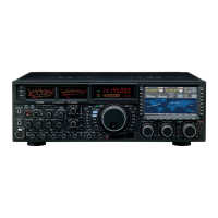
Four main antenna jacks, available for both transmission and reception, are provided on the rear panel of the transceiver.
What's more, a receive-only jack is provided, and the incoming signal path may also have a special after-market filter or
preamplifier inserted, if desired, with one-touch access.
ANTENNA SELECT switch
Selection of the desired TX/RX antenna is accomplished
by pressing the appropriate 1 ~ 4 Antenna Selection
switch (# ) on the front panel.
To engage the RX-only antenna, press the RX switch
within the Antenna Selection switch group (# ) on the
front panel. The RX-only antenna must be connected to
the corresponding “RX ANT” antenna jack on the rear
panel.
The antenna currently selected for use on the Main (VFO-
A) band will be designated by a Red LED.
The antenna currently selected for use on the Sub (VFO-B
band will be designated by an Orange LED.
If both the Main and Sub bands are utilizing the same an-
tenna, both the Red and Orange LEDs will light up on the
same antenna location.
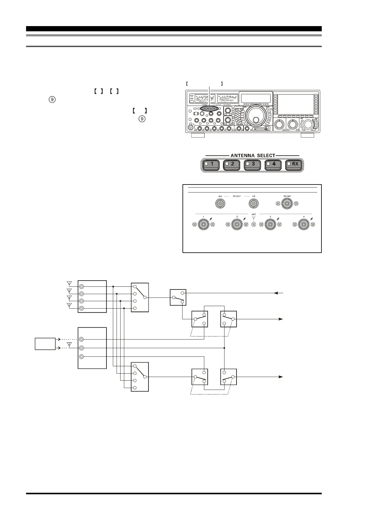
NTENNA SWITCH
(
VFO-A
)
ANT “1”
ANT “3”
ANT “2”
ANT “4”
RX ANT
RX OUT
(
MAIN
)
RX OUT
(
SUB
)
ANTENNA SWITCH
(
VFO-B
)
RX ANTENNA SWITCH
(
VFO-B
)
RX ANTENNA SWITCH
(
VFO-A
)
TX/RX RELAY
Transmitter
Section
MAIN
(
VFO-A
)
Receiver
SUB
(
VFO-B
)
Receiver
BPF
CONVENIENT FEATURES
 Loading...


