Page 17FTDX9000D OPERATION MANUAL
21
ANT 1
ANT 2
ANT 3
ANT 4
REMOTE
ON
OFF
BAND DATA 1
BAND DATA 2
GND
ALC 2
ALC 1
PTT 2
PTT 1
INPUT 1
INPUT 2
CONTROL
DC48V IN
ANT
ANT 1
ANT 2
ANT 3
INPUT 1
EXT ALC
BAND DATA 1
BAND-DATA 1
BAND-DATA 2
GND
GND
DC 48V IN
CONTROL
ALC 1
CONTROL CABLE User constructed
()
BAND DATA CABLE
()
Supplied w/VL-1000
ALC CABLE Supplied w/VL-1000
()
VP-1000
VP-1000
ANTENNA CABLE Supplied w/VL-1000
()
ANTENNA
~AC IN
BAND DATA 2
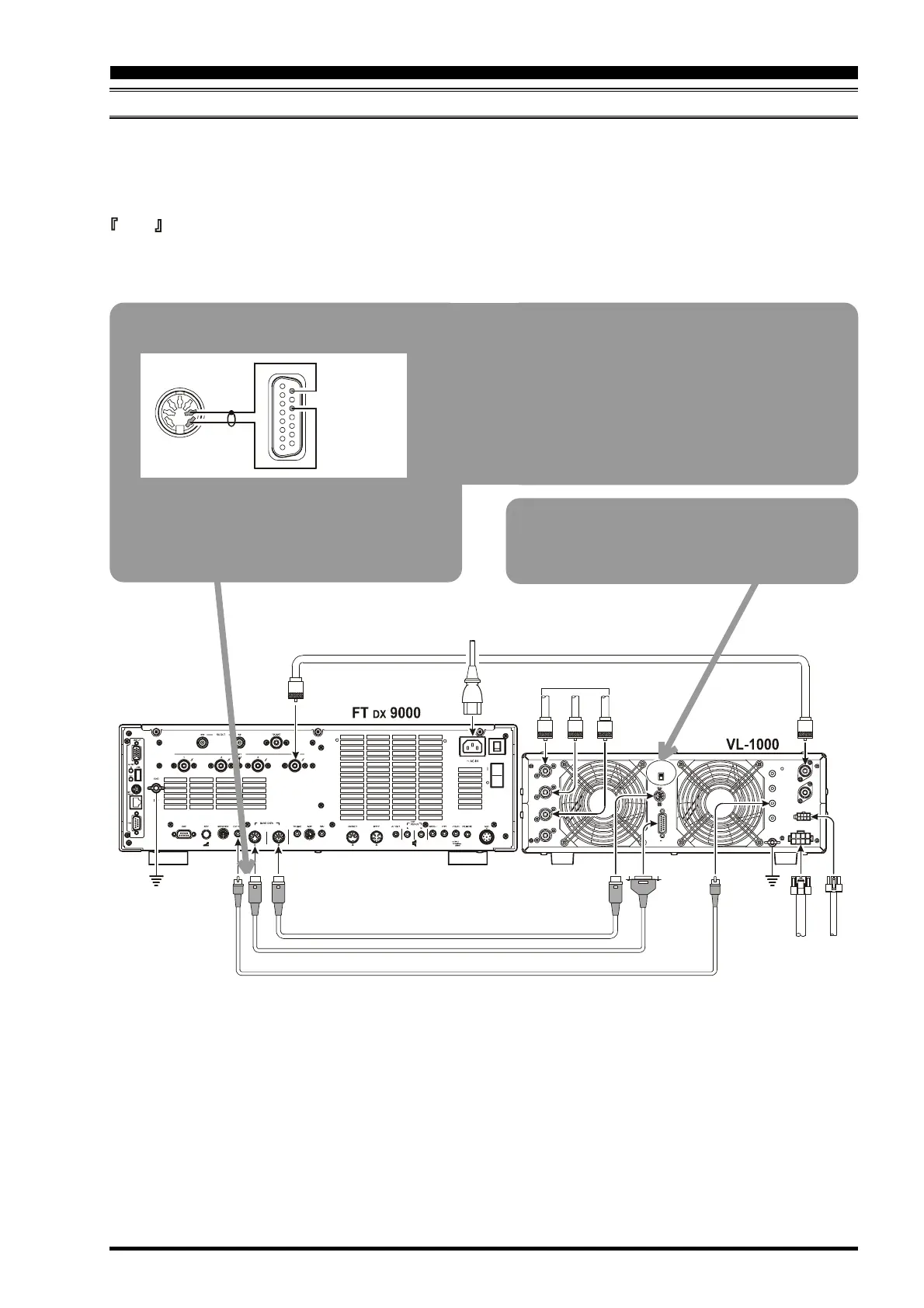
INSTALLATION AND INTERCONNECTIONS
VL-1000 Linear Amplifier Interconnections
Be sure that both the FT DX 9000 and VL-1000 are turned off, then follow the installation recommendations contained in
the illustration.
On the rear panel of the VL-1000, please set the “ATT” switch to the “ON” position. The 200-Watt power output from the
FT DX 9000D is far in excess of what is required to drive the VL-1000 to its full rated output.
Note
G Please refer to the VL-1000 Operating Manual for details regarding amplifier operation.
G Please do not attempt to connect or disconnect coaxial cables when your hands are wet.
About the CONTROL Cable
The VL-1000 may be operated with the FT DX 9000D
whether or not the CONTROL Cable is connected;
however, the CONTROL Cable allows you to tune
up the amplifier automatically my just pressing the
[F SET] or [TUNE] key on the VL-1000, so as to
transmit a carrier for tuning purposes.
To link the FT DX 9000D and VL-1000 Power
switches, set the VL-1000 REMOTE switch to the
ON position.
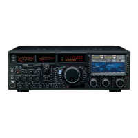
Control Cable Modification
Please cut off the RCA connector on one end of the
CONTROL Cable supplied with the VL-1000, and
install a 7-pin DIN connector in its place, accord-
ing to the illustration.
Pin 7
TRQ
Pin 3
GND
Pin 9
F SET COMMON
Pin 11
F SET 2
 Loading...


