Page 70 FTDX9000D OPERATION MANUAL
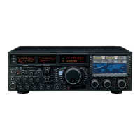
MAIN (VFO-A)
SUB (VFO-B)
MAIN(VFO-A)
WIDTH (BW) cntrol may be
observed on the TFT
SUB(VFO-B)
WIDTH (BW) cntrol may be
observed on the TFT
WIDTH (IF DSP BANDWIDTH) TUNING (SSB/CW/RTTY/PKT MODES)
The IF Width tuning system allows you to vary the width of the DSP IF passband, so as to eliminate interference. Moreover,
the bandwidth may actually be expanded from its default setting, should you wish to enhance incoming signal fidelity when
interference on the band is low.
Main (VFO-A) Band IF Width Operation
Rotate the Main (VFO-A) WIDTH knob (# ) to adjust
the bandwidth. Counter-clockwise rotation reduces the band-
width, while clockwise rotation increases the bandwidth.
Sub (VFO-B) Band IF Width Operation
1. Press the Sub (VFO-B) band’s RX switch to en-
gage Dual Receive operation.
2. Rotate the Sub (VFO-B) WIDTH knob (# ) to
adjust the bandwidth. Counter-clockwise rotation re-
duces the bandwidth, while clockwise rotation in-
creases the bandwidth.
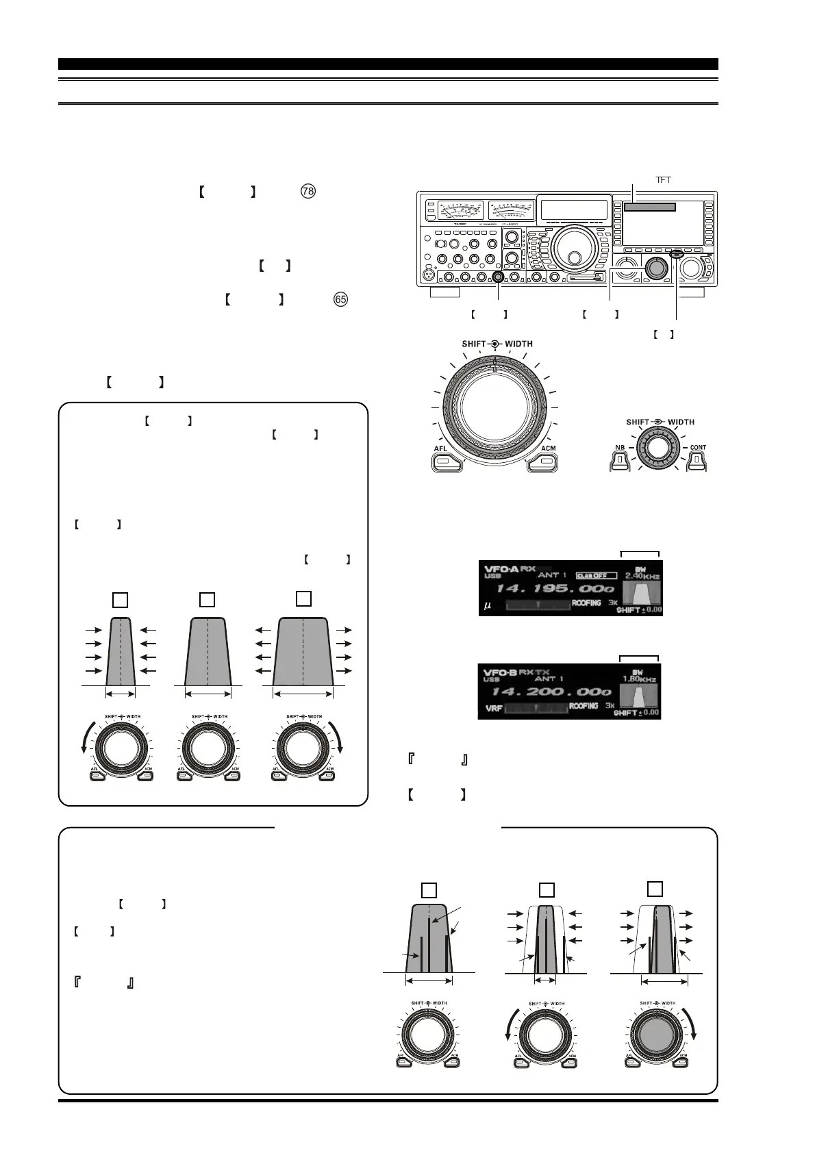
Referring to Figure B, you can see the default bandwidth
with the WIDTH control set to the 12 o’clock position.
By rotating the WIDTH knob to the left, the bandwidth will
narrow (see Figure (A)), while rotation of the WIDTH knob to
the right, as depicted in Figure (C), will widen the bandwidth.
The default bandwidths, and total bandwidth adjustment range,
will vary according to the operating mode:
SSB Mode
200 Hz ~ 2.95 kHz (bandwidth at 12 o'clock position of
WIDTH : 2.4 kHz).
CW/RTTY/PKT Modes
25 Hz ~ 2.4 kHz (bandwidth at 12 o'clock position of
WIDTH :
500 Hz).
Interference Rejection (Signals within 3 kHz)
Advice
You may observe the effects of adjustment of the
WIDTH control on the TFT.
For example, in Figure (A) you can see how interference has ap-
peared both on the high and low sides of the desired signal. By ro-
tating the
WIDTH control, as shown in Figure (B), the interfer-
ence from one side can be eliminated, and by re-positioning the
SHIFT control (Figure (C)), the interference on the opposite side
can be removed, without re-introducing the interference previously
eliminated in Figure (B).
Advice
For best interference reduction, the Width and Shift features are the
primary tools you should use. After narrowing the bandwidth (Width)
and/or adjusting the center of the passband (Shift), the Contour con-
trol may also yield additional signal-enhancement benefits on the
net residual bandwidth. What's more, the IF Notch Filter (see the
next section) may also be utilized, inconjunection with the three
other filter systems, to significant advantage.
Using IF Shift and Width Together
The IF SHift and Variable IF Width featuress together form a very effective interference-fighting filtering system.
IF BANDWIDTH IF BANDWIDTH IF BANDWIDTH
B
C
A
QRM
QRM
QRM
QRM
QRM
QRM
Desired Signal
IF BANDWIDTH IF BANDWIDTH IF BANDWIDTH
B
C
A
MAIN(VFO-A)
WIDTH knob
SUB(VFO-B)
WIDTH knob
SUB(VFO-B)
RX switch
WIDTH system may be
observed on the
 Loading...


