17
RX-V3900/DSP-AX3900
RX-V3900/
DSP-AX3900
Top cover
トップ カバー
Front panel
フロントパネル
Sub chassis unit
サブシャーシユニット
Frame top
フレーム/トップ
DCCNVT (2) P.C.B.
CB12
CB806
CB814
CB807
CB805
CB970
CB971
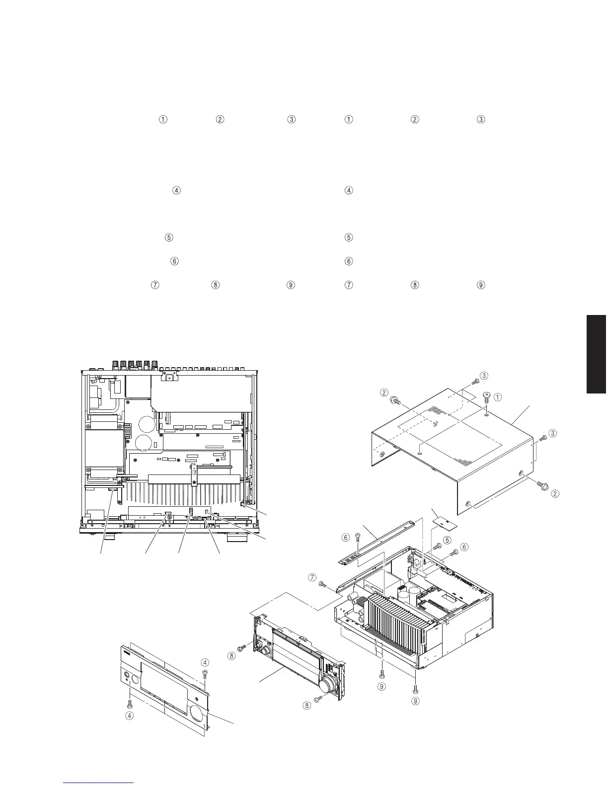
Fig. 1
■ DISASSEMBLY PROCEDURES /
分解手順
(Remove parts in the order as numbered.)
Disconnect the power cable from the AC outlet.
1. Removal of Top Cover
a. Remove 2 screws ( ), 4 screws ( ) and 5 screws ( ).
(Fig. 1)
b. Slide the top cover rearward to remove it. (Fig. 1)
2. Removal of Front Panel
Remove 6 screws ( ) and then remove the front
panel forward. (Fig. 1)
3. Removal of Sub Chassis Unit
a. Remove 2 screws ( ). (Fig. 1)
b. Remove the DCCNVT (2) P.C.B.. (Fig. 1)
c. Remove 2 screws (
) and then remove the frame
top. (Fig. 1)
d. Remove screw (
), 2 screws ( ) and 5 screws ( ).
(Fig. 1)
e. Remove CB12, CB805-807, CB814, CB970 and CB971.
(Fig. 2)
d. Remove the sub chassis unit forward. (Fig. 1)
(番号順に部品を取り外してください。)
AC 電源コンセントから、電源コードを抜いてください。
1. トップカバーの外し方
a. のネジ2本、 のネジ4本、 のネジ 5 本を外し
ます。(Fig.1)
b. トップカバーを後方へスライドさせ、取り外します。
(Fig.1)
2. フロントパネルの外し方
のネジ 6 本を外し、フロントパネルを前方に外しま
す。(Fig.1)
3. サブシャーシユニットの外し方
a. のネジ2本を外します。(Fig.1)
b. DCCNVT(2)P.C.B. を取り外します。(Fig.1)
c.
のネジ 2 本を外し、フレーム/トップを取り外しま
す。(Fig.1)
d.
のネジ1本、 のネジ2本、 のネジ 5 本を外し
ます。(Fig.1)
e. CB12、CB805 〜 CB807、CB814、CB970、CB971 を外
します。(Fig.2)
f. サブシャーシユニットを前方に取り外します。(Fig.1)
Fig. 2

 Loading...