22
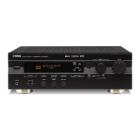
RX-V3900/DSP-AX3900
RX-V3900/
DSP-AX3900
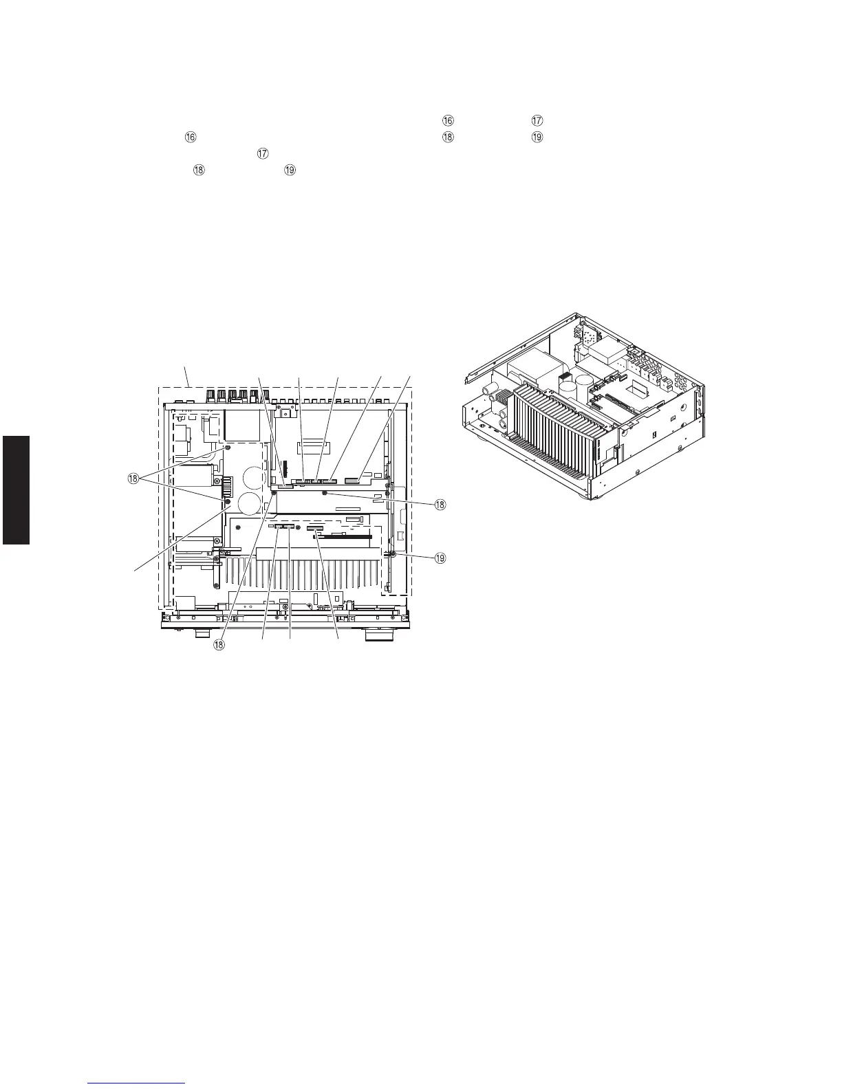
CB17 CB16CB20
CB407 CB409CB406CB303
CB405
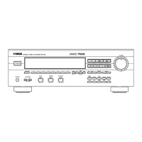
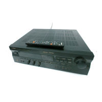
Rear unit
リアユニット
MAIN (2)
P. C . B .
Fig. 8
6. Removal of Rear Unit
a. Remove 10 (U, C, T, K, A, B, G, E models) / 12 (R, L
models) screws (
) and 4 (U, C, R, T, A, B, G, E, L
models) / 2 (K model) screws (
). (Fig. 6)
b. Remove 4 screws (
) and screw ( ). (Fig. 8)
c. Remove CB16, CB17, CB20, CB303, CB405-407 and
CB409. (Fig. 8)
d. Remove the rear unit and MAIN (2) P.C.B.. (Fig. 8)
6. リアユニットの外し方
a. のネジ 9 本、 のネジ 4 本を外します。(Fig.6)
b.
のネジ 4 本、 のネジ 1 本を外します。(Fig.8)
c. CB16、CB17、CB20、CB303、CB405 〜 407、CB409 を外
します。(Fig.8)
d. リアユニットおよび MAIN(2)P.C.B. を取り外します。
 Loading...