(22) Drive-in Direction of the Roll Pin: Set the
crack
at
a
90" position from the load direction.
When driving in dually, the inside roll pin crack
should be positioned at
18O0from the outside.
roll pin crack.
2. TRANSMISSION ASSEMBLY
2-1 P.T.O. Driving
Shaft
Assembly
(1)
Fit the (2) circlip 25 to the (1)
P.T.O.
driv-
ing shaft.
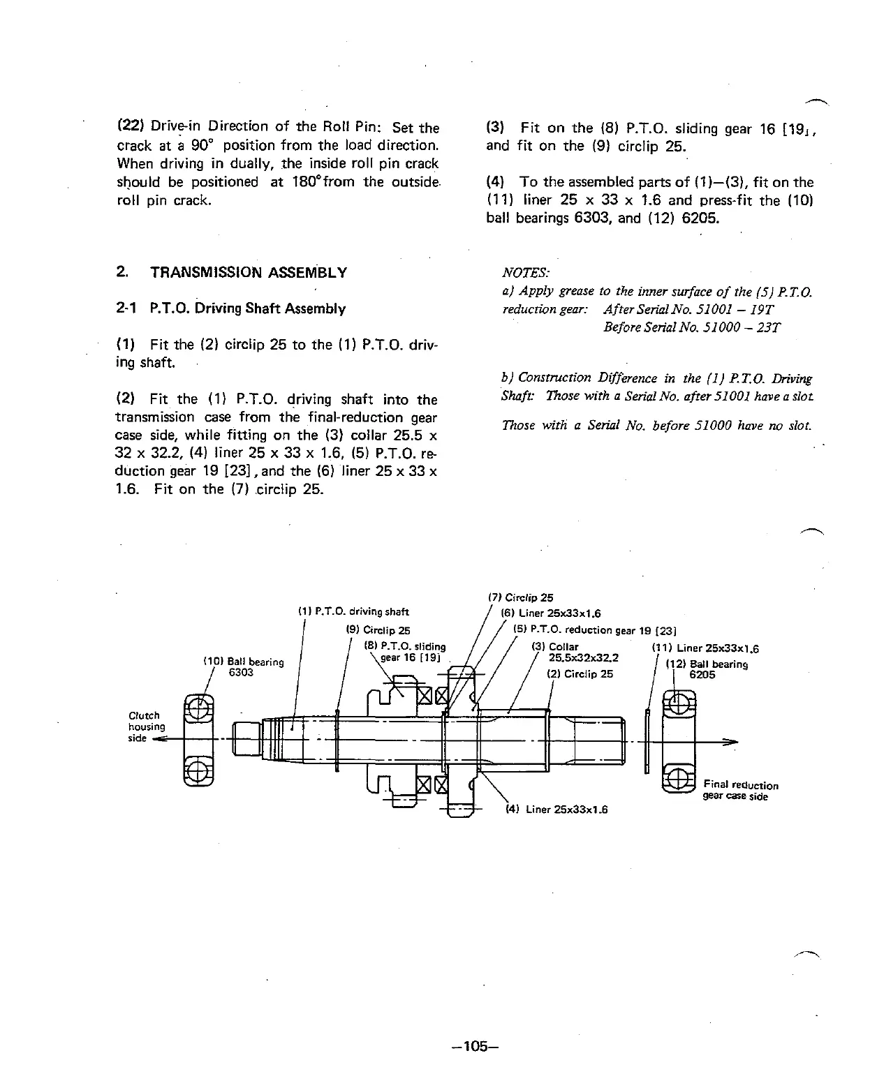
(2)
Fit the (1)
P.T.O.
driving shaft into the
transmission case from the final-reduction gear
case side, while fitting on the
(3) collar 25.5
x
32
x
32.2,
(4)
liner 25
x
33
x
1.6, (5)
P.T.O.
re-
duction gear 19
1231, and the (6) liner 25
x
33
x
1.6.
Fit on the
(7)
circlip 25.
Clutch
housing
side
c
(3)
Fit on the
(8)
P.T.O.
sliding gear 16 [19,,
and fit on the
(9)
circlip 25.
(4)
To the assembled parts of (1)-(3), fit on the
(1 1) liner 25
x
33
x
1.6 and press-fit the (10)
ball bearings 6303, and (12) 6205.
NOTES:
a]
Apply
grease to the inner surface of rhe (5) P.T.O.
reduction
gear
Afrer SeriaINo. 51001
-
19T
Before Serial No. 51 000
-
23T
b] Consmcrion Difference in rhe (1) P.T.0. Driving
Shaft: Those
wirh a Serial No. after 51 001 have a slot
Those wirh a Serial No. before 51000 have no slot
i'T
25
(1
1
P.T.O.
driving
shaft
161
Liner
25~33~1.6
1
191
Cinlip
25 (51
P.T.O.
reduction
gear
19 I231
~ ~
(111
Liner
25~33~1.6
Final
reauction
gear
case
ride
U
i41
Liner
25~33~1.6
 Loading...