('Refer
to
Note below)
NOTES:
(1)
To replace the small end bushings, press-fir in new bushings.
During rhe
operation be sure
rhar there is no peeling or contraction of the bushings.
Mea-
sure the inner diameters afrer rhe new bushings have been
press-fitred in position If the
diamerer is roo small,
it
should be corrected, using a reamer. When press-firrng new
bushings
into position, be sure to align rhe oil passages of the bushings with those of rhe
connecting rod.
Illurnation
(2)
The clearance referred to in Irem
3
above is rhe difference befween rhe outer
diameter of
the piston pin and rhe inner diameter of the bushings obtained by measure-
ments.
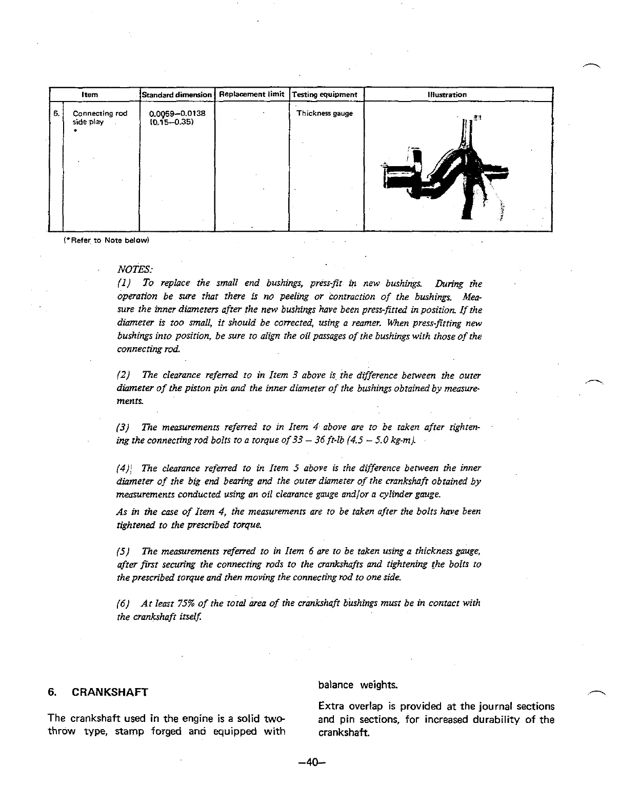
Testing equipment
Thickness
gauge
(3)
The measurements referred ro in Irem 4 above are to be raken afrer righren-
ing rhe connecringrod bolrs to a rorque of 33
-
36 ft-lb (4.5
-
5.0 kg-m).
Item
(4);
The clearance referred to in Irem 5 above is rhe difference benveen rhe inner
diameter of rhe big end bearing and the outer diameter
0.f
the crankshafr obtained by
measurements conducted using an oil
clemce gauge and/or a cylinder gouge.
As in
the case of Item 4, rhe measuremenrs are to be raken after the bolrs have been
tightened
to the prescribed rorque
Standarddimemion
0.0Q59-0.0138
10.15-0.35)
6.
(5
The measuremenn refwed ro in Item 6 are ro be taken using a thickness gauge,
afrer
psr securing the connecting rods ro rhe crankshafrs and tighrening rhe bolts to
rhe prescribed rorque and rhen moving the connectingrod ro one side
Replacement limif
Connecting
rod
ilde
play
(6)
Ar least 75% of rhe roral area of the crankshafr bushings musr be in contact wirh
the crankshaft
irselx
6.
CRANKSHAFT
balance weights.
n
Extra overlap
is
provided at the journal sections
The crankshaft used in the engine
is
a solid
two-
and pin sections, for increased durability of the
throw type, stamp forged and equipped with crankshaft.
 Loading...