5.
INSTRUCTIONS FOR DISASSEMBLY
(1)
Do not keep the unit in storage under dusty,
AND ASSEMBLY
damp, and high temperature conditions.
(Refer to diagram on p.
72)
(2)
In case dust, dirt, water, oil, etc. are
de-
[Disassembly]
posited on the generator and lead connections,
clean the necessary parts before use.
(1)
Remove hexagon nut (c);
(with attaching the top of the shaft ("side);
(3)
Keep the appropriate belt tension, to avoid
do not put stress on the flywheel)
belt slippage.
(2)
Dismantle the flywheel (a);
(lightly tap the top of the shaft with
a
wooden hammer)
(3)
Separate the lead wire from each diode ter-
minal
(A,
6,
C,
D)
with a soldering iron;
(do not apply the soldering iron to the ter-
minals for a long time or
it
will damage the
diodes)
(4)
Remove the set screws
(h),
and proceed to
diodes.
(5)
Remove the set screw (d), and remove
armature coil
(el.
[Assembly]
Follow the instructions above reversely.
6.
MAINTENANCE AND INSPECTION
[Current Limiter]
This is used coupled with the generator. Refer to
the section on the generator, for the specifica-
tions, diagram, and handling instructions.
Current limiter forms one unit contained in resin
mold. In the case of a failure, replace current
limiter
as
a unit.
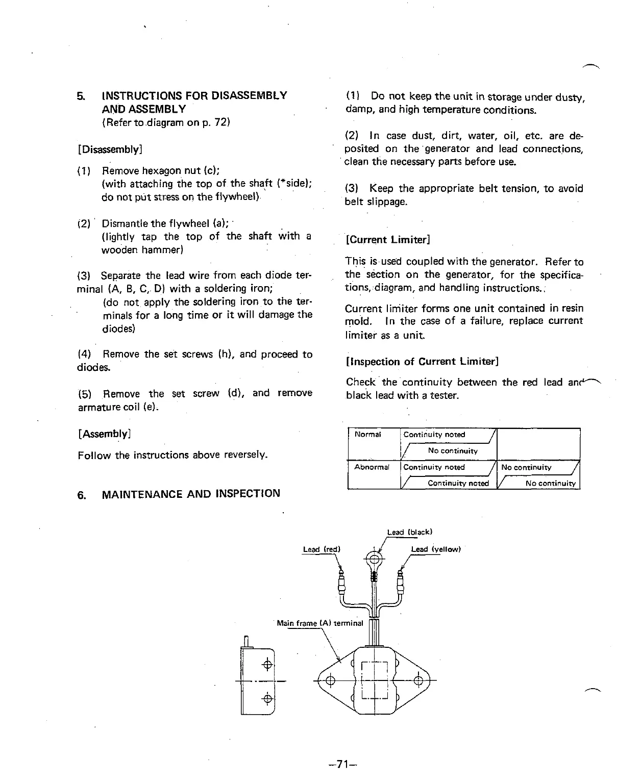
[Inspection of Current Limiter]
Checkthecontinuity between the red lead
an-
black lead with
a
tester.
No
continuity
Lead Iblack)
I

 Loading...