16 UL Standards
YASKAWA TOEPC71061723A YASKAWA AC Drive CR700 Quick Start Guide 113
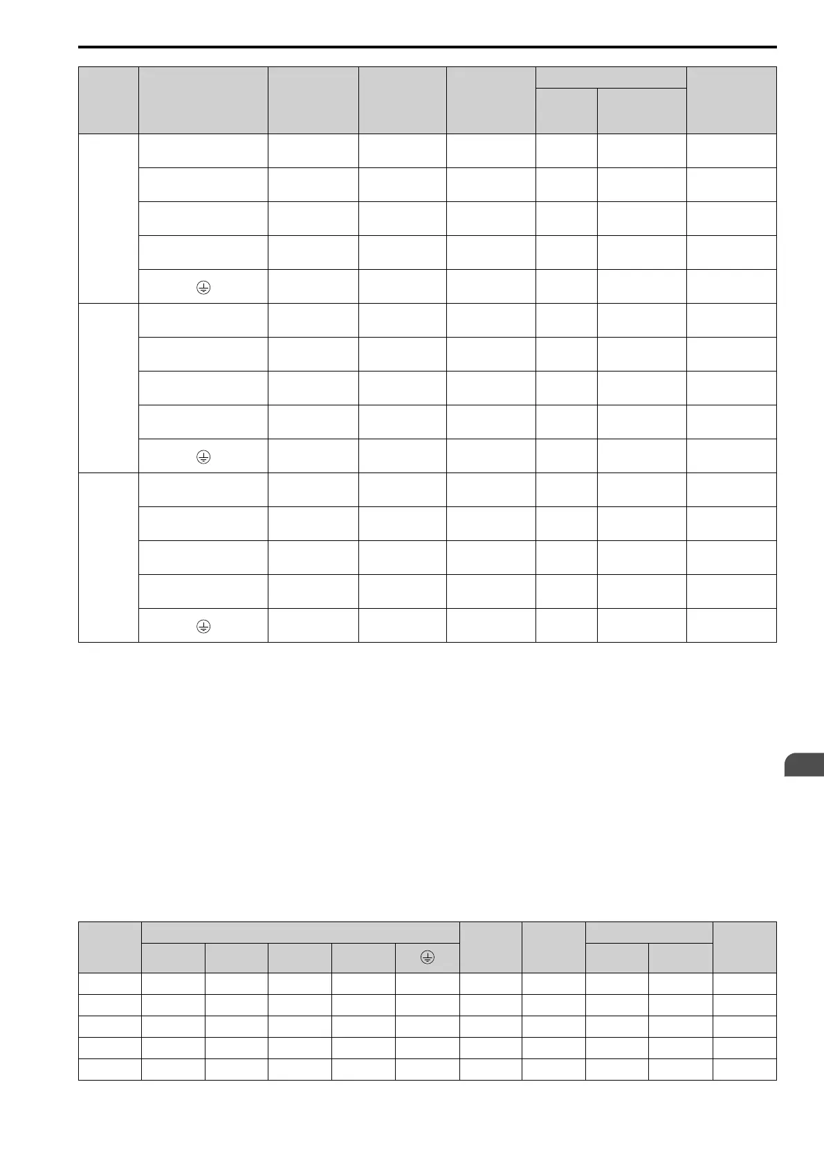
Model Terminal
Recomm. Gauge
AWG, kcmil
Applicable
Gauge
(IP20 Applicable
Gauge
*1
)
AWG, kcmil
Wire Stripping
Length
*2
mm
Terminal Screw
Tightening
Torque
N∙m (lbf∙in)
Size Shape
4414
R/L1, S/L2, T/L3, R1/L11, S1/
L21, T1/L31
250 × 4P
2/0 - 300 × 4P
(250 - 300 × 4P)
- M12 Hex self-locking nut
35
(310)
U/T1, V/T2, W/T3 4/0 × 4P
2/0 - 300 × 4P
(250 - 300 × 4P)
- M12 Hex self-locking nut
35
(310)
-, +1 4/0 × 4P
3/0 - 400 × 4P
(300 - 400 × 4P)
- M12 Hex self-locking nut
35
(310)
+3 3/0 × 4P
2 - 4/0
(4/0 × 4P)
- M12 Hex self-locking nut
35
(310)
1/0
1/0 - 300
(-)
- M12 Hex bolt (slotted)
32 - 40
(283 - 354)
4453
R/L1, S/L2, T/L3, R1/L11, S1/
L21, T1/L31
250 × 4P
2/0 - 300 × 4P
(250 - 300 × 4P)
- M12 Hex self-locking nut
35
(310)
U/T1, V/T2, W/T3 4/0 × 4P
2/0 - 300 × 4P
(250 - 300 × 4P)
- M12 Hex self-locking nut
35
(310)
-, +1 300 × 4P
3/0 - 400 × 4P
(300 - 400 × 4P)
- M12 Hex self-locking nut
35
(310)
+3 3/0 × 4P
2 - 4/0 × 4P
(4/0 × 4P)
- M12 Hex self-locking nut
35
(310)
2/0
2/0 - 300
(-)
- M12 Hex bolt (slotted)
32 - 40
(283 - 354)
4605
R/L1, S/L2, T/L3, R1/L11, S1/
L21, T1/L31
300 × 4P
2/0 - 300 × 4P
(250 - 300 × 4P)
- M12 Hex self-locking nut
35
(310)
U/T1, V/T2, W/T3 300 × 4P
2/0 - 300 × 4P
(250 - 300 × 4P)
- M12 Hex self-locking nut
35
(310)
-, +1 400 × 4P
3/0 - 400 × 4P
(300 - 400 × 4P)
- M12 Hex self-locking nut
35
(310)
+3 4/0 × 4P
2 - 4/0 × 4P
(4/0 × 4P)
- M12 Hex self-locking nut
35
(310)
2/0
2/0 - 300
(-)
- M12 Hex bolt (slotted)
32 - 40
(283 - 354)
*1 For IP20 protection, use wires that are in the range of applicable gauges.
*2 Remove insulation from the ends of wires to expose the length of wire shown.
*3 For wire gauges more than AWG 8, tighten to a tightening torque of 4.1 N∙m to 4.5 N∙m (36 lbf∙in to 40 lbf∙in).
*4 Terminals - and +1 have two screws. The Recommended Gauge is the wire gauge for one terminal.
*5 A junction terminal is necessary to connect a braking resistor unit (LKEB-series) to terminals B1 and B2.
■ Closed-Loop Crimp Terminals
To comply with UL standards on drive models 2215 to 2415 and 4180 to 4605, use UL-approved closed-loop
crimp terminals. Use the tools recommend by the terminal manufacturer to crimp the closed-loop crimp terminal.
Yaskawa recommends closed-loop crimp terminals from JST Mfg. Co., Ltd. and insulation caps from Tokyo DIP
Co., Ltd. Contact Yaskawa or your nearest sales representative to make an order.
Refer to Table 16.4 to select crimp terminals as specified by drive model and wire gauge.
Note:
To comply with UL standards, use only insulated crimp terminals or crimp terminals with insulation tubing. Use UL-Listed, vinyl-
coated insulated copper wires for operation with a continuous maximum permitted temperature of 75 °C at 600 V.
Table 16.4 Closed-Loop Crimp Terminals and Insulation Caps
Model
Recomm. Gauge (AWG, kcmil)
Terminal
Screw Size
Crimp
Terminal
Model
Crimping Tool
Insulation
Cap Model
R/L1, S/L2,
T/L3
U/T1, V/T2,
W/T3
-, +1 +3 Tool Model Die Jaw
2003 - 2018 - - - - 10 M4 R5.5-4 YA-4 AD-900 TP-005
2025, 2033 - - - - 8 M5 R8-5 YA-4 AD-901 TP-008
2047 - - - - 6 M6 R14-6 YA-4 AD-902 TP-014
2060 - 2088 - - - - 6 M6 R14-6 YA-4 AD-902 TP-014
2115 - - - - 4 M6 R22-6 YA-5 AD-953 TP-022
EN
 Loading...


