13 Troubleshooting
YASKAWA TOEPC71061723A YASKAWA AC Drive CR700 Quick Start Guide 71
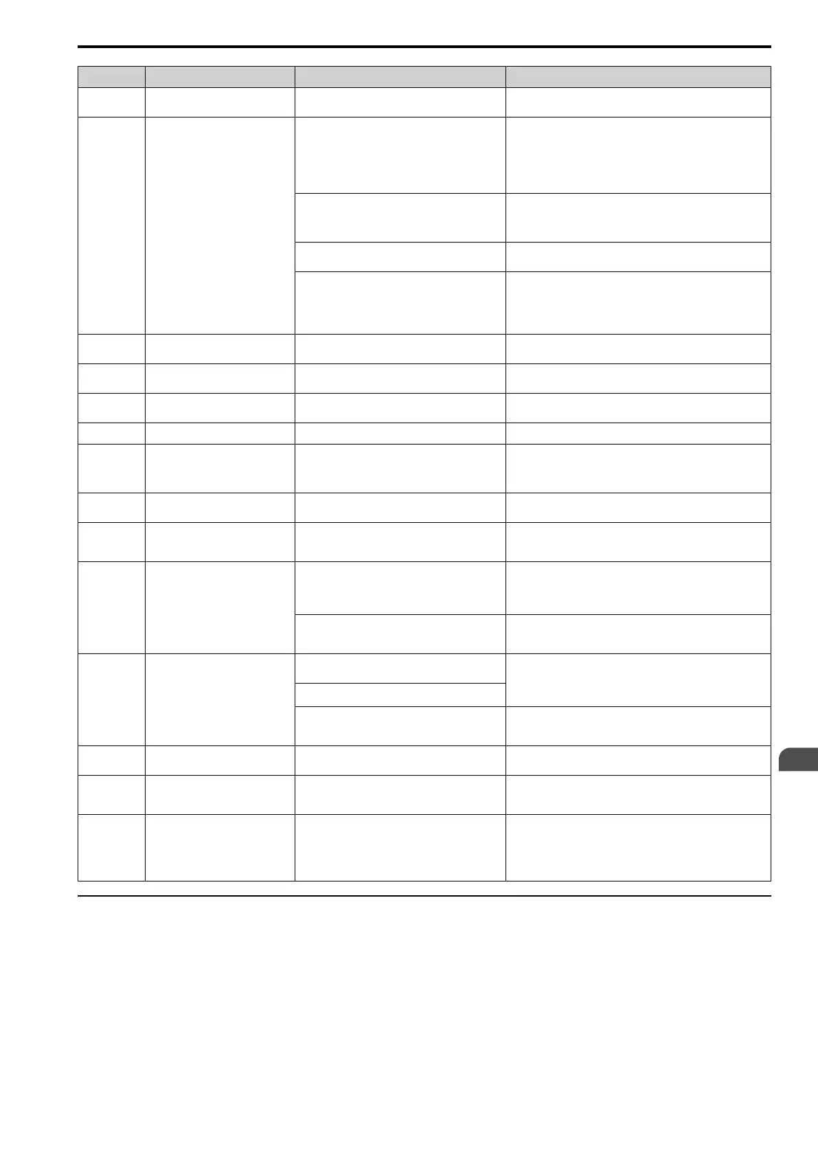
Code Name Causes Possible Solutions
oS Overspeed
Overshoot is occurring. Decrease C5-01 [ASR Proportional Gain 1] and increase C5-02
[ASR Integral Time 1].
ov DC Bus Overvoltage
There are surge voltages in the input power supply. Connect a DC reactor to the drive.
Note:
If you turn the phase advancing capacitors ON and OFF and
use thyristor converters in the same power supply system,
there can be surge voltages that irregularly increase the input
voltage.
The drive output cable or motor is shorted to
ground. (The current short to ground is charging the
main circuit capacitor of the drive through the
power supply.)
1. Examine the motor main circuit cable, terminals, and motor
terminal box, and then remove ground faults.
2. Re-energize the drive.
The power supply voltage is too high. Decrease the power supply voltage so that it matches the drive
rated voltage.
A drive malfunction occurred due to electrical
interference.
• Check the control circuit lines, main circuit lines, and ground
wiring, and minimize the effects of electrical interference.
• Check whether a magnetic contactor is the electrical
interference source, and use Surge Protective Device if
necessary.
PASS Modbus Communication Test
The MEMOBUS/Modbus communications test is
complete.
The PASS display will turn off after communications test mode is
cleared.
PF Input Phase Loss
There is a phase loss in the drive input power. Examine for wiring errors or disconnected wires in main circuit
drive input power, and repair problems.
PGo Encoder (PG) Feedback Loss
The encoder cable is incorrectly wired or
disconnected.
Examine for wiring errors or disconnected wires in the encoder
cable, and repair problems.
PGoH Encoder (PG) Hardware Fault
The encoder cable is disconnected. Correct any disconnected wires in the encoder cable.
rEvL Rev Limit (rEvL)
The terminal assigned to H1-xx = 33, 34 [MFDI
Function Select = Rev Limit (rEvL), Reverse Travel
Limit (N.C.)] is input, the Run command has been
disabled.
Turn OFF the Travel Limit to input the Forward run command.
rUn Motor Switch during Run
The drive received a Motor 2/3 Selection [H1-xx =
16 or 39] during run.
Review the sequence to ensure that Motor 2/3 Selection is input
while the drive is stopped.
SE Modbus Test Mode Error
MEMOBUS/Modbus communications self-
diagnostics [H1-xx = 67] was done while the drive
was running.
Stop the drive and do MEMOBUS/Modbus communications self-
diagnostics.
STo Safe Torque OFF
Safe Disable inputs H1-HC and H2-HC are open. • Make sure that the Safe Disable signal is input from an
external source to terminal H1-HC and H2-HC.
• When the Safe Disable function is not in use, connect
terminals H1-HC and H2-HC.
There is internal damage to the two Safe Disable
channels.
Replace the control board or the drive. For information about
replacing the control board, contact Yaskawa or your nearest sales
representative.
SToF Safe Torque OFF Hardware
One of the two terminals H1-HC or H2-HC
received the Safe Disable input signal.
The Safe Disable input signal is wired incorrectly.
• Make sure that the Safe Disable signal is input from an
external source to terminal H1-HC or H2-HC.
• When the Safe Disable function is not in use, connect
terminals H1-HC and H2-HC.
There is internal damage to one Safe Disable
channel.
Replace the control board or the drive. For information about
replacing the control board, contact Yaskawa or your nearest sales
representative.
TiM Keypad Time Not Set
There is a battery in the LCD keypad, but the date
and time are not set.
Set the date and time with the LCD keypad.
TrPC IGBT Maintenance Time (90%)
The IGBT is at 90% of its expected performance
life.
Replace the IGBT or the drive. For information about replacing
the control board, contact Yaskawa or your nearest sales
representative.
Uv Undervoltage
The drive input power voltage is changing too
much.
• Review the power supply voltage so that it matches the drive
rated voltage.
• Make the drive input power stable.
• If the input power supply is good, examine the magnetic
contactor on the main circuit side for problems.
◆ Parameter Setting Errors
Parameter setting errors occur when multiple parameter settings do not agree, or when parameter setting values
are not correct. Refer to the table in this section, examine the parameter setting that caused the error, and remove
the cause of the error. You must first correct the parameter setting errors before you can operate the drive. The
drive will not send notification signals for the faults and alarms when these parameter setting errors occur.
EN
 Loading...