9 Electrical Installation
YASKAWA TOEPC71061723A YASKAWA AC Drive CR700 Quick Start Guide 31
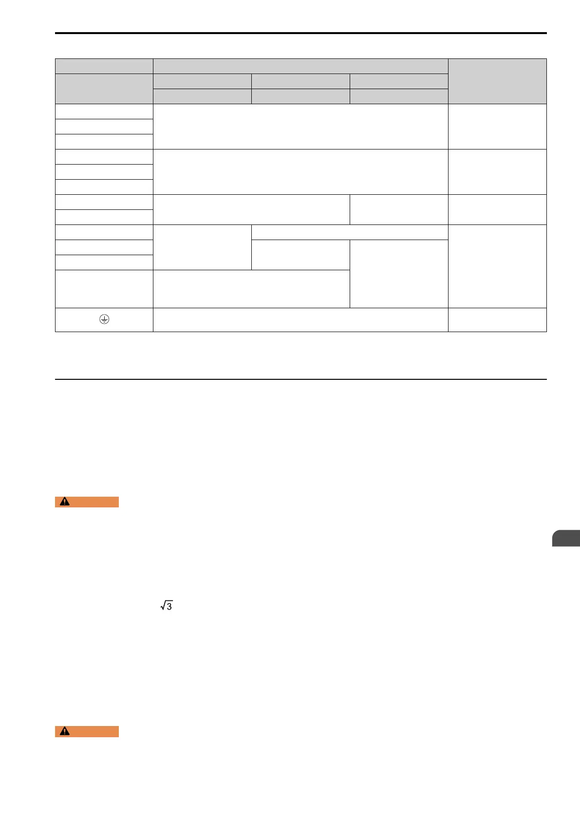
Table 9.3 Main Circuit Terminal Functions
Terminals Name
Function
Model
2003 - 2075 2088 - 2115 2145 - 2415
4002 - 4039 4045 - 4150 4180 - 4605
R/L1
Main circuit power supply input
Connecting a commercial power
supply.
S/L2
T/L3
U/T1
Drive output Connecting a motor.V/T2
W/T3
B1
Braking resistor connection -
Connecting a braking resistor or
braking resistor unit.
B2
+2
• DC power supply input (+1
and -)
• DC reactor connection (+1 and
+2)
-
Connecting peripheral devices
such as:
• DC power input
• Braking unit
• DC Reactor
Note:
Remove the jumper between
the terminals +1 and +2 when
connecting a DC reactor.
+1
DC power supply input (+1 and -)
• DC power supply input (+1
and -)
• Braking unit connection (+3
and -)
-
+3 -
• 200 V: D class grounding (ground to 100 Ω or less)
• 400 V: C class grounding (ground to 10 Ω or less)
Grounding.
Note:
Use terminals B1 and - to connect a control unit (CDBR-type) to drive models 2003 to 2115 and 4002 to 4150 with built-in braking
transistors.
◆ Main Circuit Wire Gauges and Tightening Torques
Select the correct wires for main circuit wiring.
Refer to Wire Gauges and Tightening Torques on page 79 for wire gauges and tightening torques as specified by
European standards.
Refer to Wire Gauges and Tightening Torques on page 104 for wire gauges and tightening torques as specified by
UL standards.
■ Wire Selection Precautions
WARNING
Electrical Shock Hazard. Make sure that the protective ground wire complies with technical standards and
local safety regulations. The IEC/EN 61800-5-1:2007 standard specifies that you must wire the power supply to automatically
de-energize when the protective ground wire disconnects. You can also connect a protective ground wire that has a minimum
cross-sectional area of 10 mm
2
(copper wire) or 16 mm
2
(aluminum wire). If you do not obey the standards and regulations, it
can cause serious injury or death. The leakage current of the drive will be more than 3.5 mA in drive models 2xxxB, 4xxxB, and
4317A to 4605A.
Think about line voltage drop before selecting wire gauges. Select wire gauges that drop the voltage by 2% or less
of the rated voltage. Increase the wire gauge and the cable length when the risk of voltage drops increases.
Calculate line voltage drop with this formula:
Line voltage drop (V) = × wire resistance (Ω/km) × wiring distance (m) × motor rated current (A) × 10
-3
.
■ Precautions during Wiring
• Use terminals B1 and - to connect braking units to drives that have built-in braking transistors (models 2003 to
2115 and 4002 to 4150). Use terminals +3 and - to connect braking units to drives that do not have built-in
braking transistors.
• Refer to “Yaskawa AC Drive Option Braking Unit, Braking Resistor Unit Instruction Manual
(TOBPC72060001)” for information about wire gauges and tightening torques to connect braking resistor units
or braking units.
• Use terminals +1 and - to connect a regenerative converter or regenerative unit.
WARNING
Fire Hazard. Do not connect a braking resistor to terminals +1 or -. Use terminals B1 and B2 for the braking
resistor connections. If you connect a braking resistor to the incorrect terminals, it can cause damage to the drive and braking
circuit and serious injury or death.
EN
 Loading...