9 Electrical Installation
YASKAWA TOEPC71061723A YASKAWA AC Drive CR700 Quick Start Guide 41
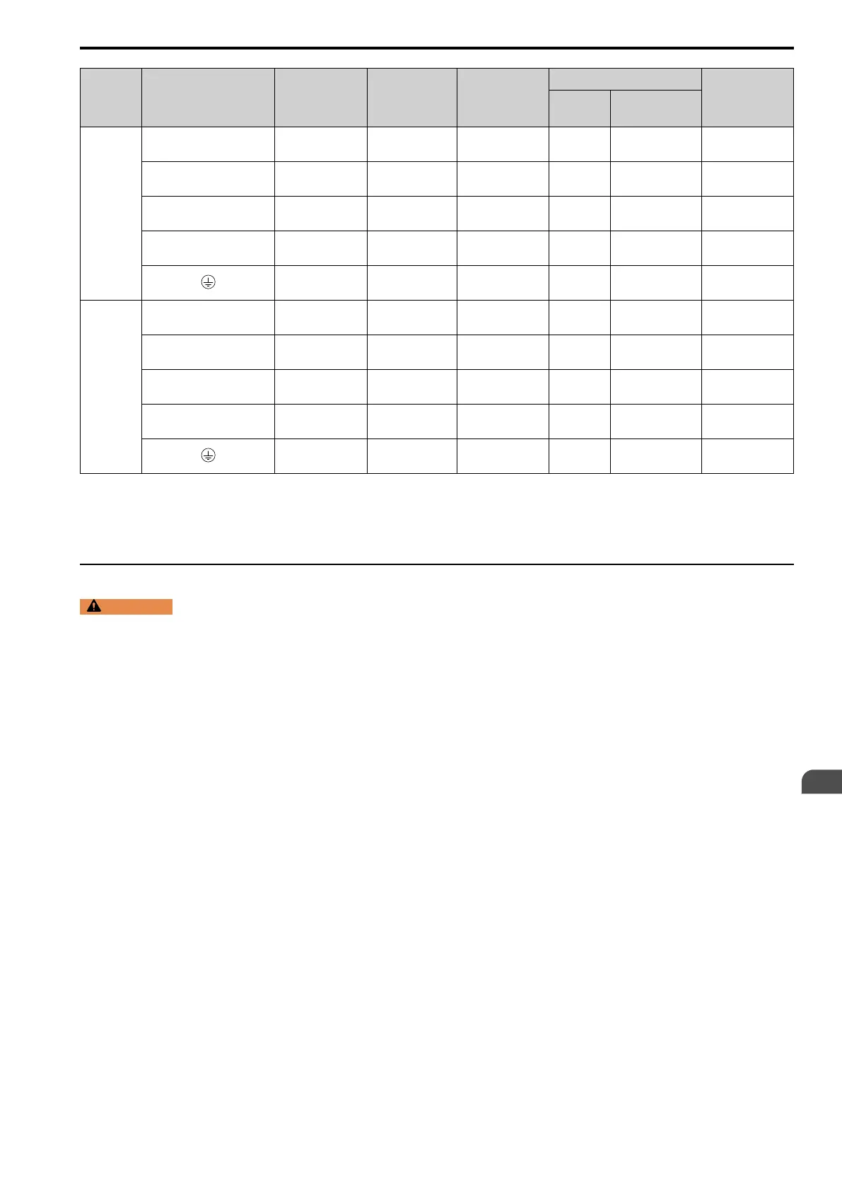
Model Terminal
Recomm. Gauge
mm
2
Applicable Gauge
(IP20 Applicable
Gauge
*1
)
mm
2
Wire Stripping
Length
*2
mm
Terminal Screw
Tightening
Torque
N∙m (lbf∙in)
Size Shape
4453
R/L1, S/L2, T/L3
R1/L11, S1/L21, T1/L31
125 × 4P
60 - 125 × 4P
(125 × 4P)
- M12 Hex self-locking nut
35
(310)
U/T1, V/T2, W/T3 100 × 4P
60 - 150 × 4P
(125 - 150 × 4P)
- M12 Hex self-locking nut
35
(310)
-, +1 100 × 4P
80 - 150 × 4P
(150 × 4P)
- M12 Hex self-locking nut
35
(310)
+3 80 × 4P
30 - 125 × 4P
(100 - 125 × 4P)
- M12 Hex self-locking nut
35
(310)
60
60 - 150
(-)
- M12 Hex bolt (slotted)
32 - 40
(283 - 354)
4605
R/L1, S/L2, T/L3
R1/L11, S1/L21, T1/L31
125 × 4P
60 - 125 × 4P
(125 × 4P)
- M12 Hex self-locking nut
35
(310)
U/T1, V/T2, W/T3 100 × 4P
60 - 150 × 4P
(125 - 150 × 4P)
- M12 Hex self-locking nut
35
(310)
-, +1 125 × 4P
80 - 150 × 4P
(150 × 4P)
- M12 Hex self-locking nut
35
(310)
+3 100 × 4P
30 - 125 × 4P
(100 - 125 × 4P)
- M12 Hex self-locking nut
35
(310)
60
60 - 150
(-)
- M12 Hex bolt (slotted)
32 - 40
(283 - 354)
*1 For IP20 protection, use wires that are in the range of applicable gauges.
*2 Remove insulation from the ends of wires to expose the length of wire shown.
*3 For wire gauges more than 30 mm
2
, tighten to a tightening torque of 4.1 N∙m to 4.5 N∙m (36 lbf∙in to 40 lbf∙in).
*4 Terminals - and +1 have two screws. The Recommended Gauge is the wire gauge for one terminal.
*5 A junction terminal is necessary to connect a braking resistor unit (LKEB-series) to terminals B1 and B2.
◆ Motor and Main Circuit Connections
WARNING
Electrical Shock Hazard. Do not connect terminals R/L1, S/L2, T/L3, U/T1, V/T2, W/T3, -, +1, +2, +3, B1, or
B2 to the ground terminal. If you connect these terminals to earth ground, it can cause damage to the drive or serious injury or
death.
EN
 Loading...