9 Electrical Installation
44 YASKAWA TOEPC71061723A YASKAWA AC Drive CR700 Quick Start Guide
Table 9.5 Control Circuit Output Terminals
Mode Terminals Name (Default) Function (Signal Level)
Fault relay output
MA
N.O. output
(Fault) • Relay output
• DC30 V, 10 mA to 1 A
• AC250 V, 10 mA to 1 A
• Minimum load: 5 V, 10 mA (Reference value)
MB
N.C. output
(Fault)
MC Digital output common
Digital Outputs
M1
Digital Outputs
(Brake Release Command)
• Relay output
• DC30 V, 10 mA to 1 A
• AC250 V, 10 mA to 1 A
• Minimum load: 5 V, 10 mA (Reference value)
Note:
Switching life is estimated at 8,000,000 times (assumes 30 mA, inductive load) or 200,000
times (assumes 1 A, resistive load). When switching inductive load such as relay coils,
connect surge absorbing element in parallel against the load for effective protection of relay
contact.
M2
M3
Digital Outputs
(During run)
M4
M5
Digital Outputs
(Speed agree 1)
M6
Multi-function
photocoupler
output
P1
Multi-function photocoupler output
(Drive operation ready (READY))
• Photocoupler output
• 48 V, 2 mA to 50 mA
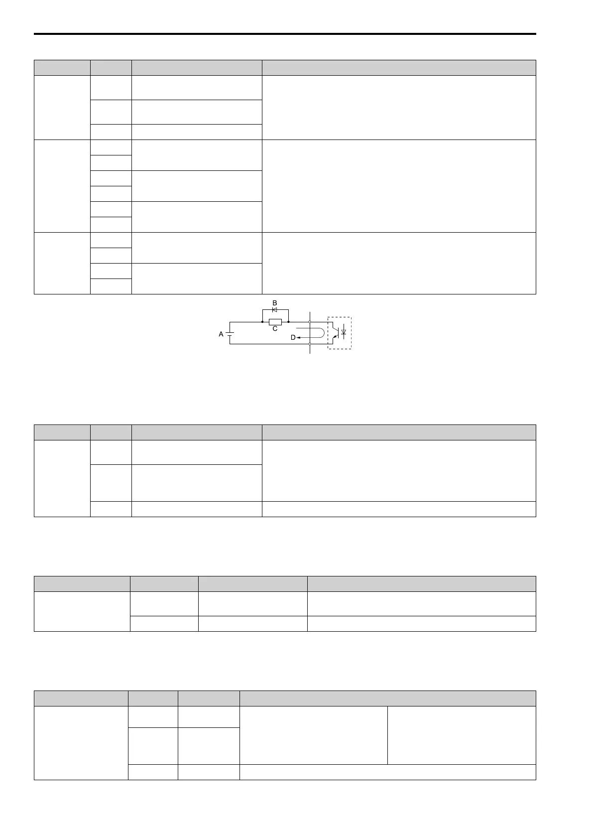
Note:
Connect a flywheel diode as shown in Figure 9.17 when driving a reactive load such as a
relay coil. Ensure the diode rating is greater than the circuit voltage.
C1
P2
Multi-function photocoupler output
(Minor Fault)
C2
A - External power, 48 V max.
B - Flywheel diode
C - Coil
D - 50 mA or less
Figure 9.17 Connecting a Flywheel Diode
Table 9.6 Control Circuit Monitor Output Terminals
Mode Terminals Name (Default) Function (Signal Level)
Monitor output
FM
Analog monitor output 1
(Output frequency)
Voltage output
• 0 V to +10 V/0% to 100%
• -10 V to +10 V/-100% to +100%
Note:
Select with H4-07 [MFAO Term FM Signal Level Select] or H4-08 [MFAO Term AM Signal
Level Select].
AM
Analog monitor output 2
(Output current)
AC Monitor common 0 V
■ External Power Supply Input Terminals
Refer to Table 9.7 for a list of the functions of the external power supply input terminals.
Table 9.7 External Power Supply Input Terminals
Type Terminal Name (Default) Function
External Power Supply Input
Terminals
PS External 24 V power supply input
Supplies backup power to the drive control circuit, keypad, and option board.
21.6 VDC to 26.4 VDC, 700 mA
AC External 24 V power supply ground 0 V
■ Serial Communication Terminals
Refer to Table 9.8 for a list of serial communication terminals and functions.
Table 9.8 Serial Communication Terminals
Type Terminal Terminal Name Function (Signal Level)
Modbus Communication
D+
Communication
input/output (+)
MEMOBUS/Modbus communications
Use an RS-485 cable to connect the drive.
Note:
Set DIP switch S2 to ON to enable the
termination resistor in the last drive in a
MEMOBUS/Modbus network.
• RS-485
• MEMOBUS/Modbus communication protocol
• Maximum 115.2 kbps
D-
Communication
output (-)
AC Shield ground
0 V
 Loading...