12 Drive Control, Duty Modes, and Programming
YASKAWA TOEPC71061723A YASKAWA AC Drive CR700 Quick Start Guide 57
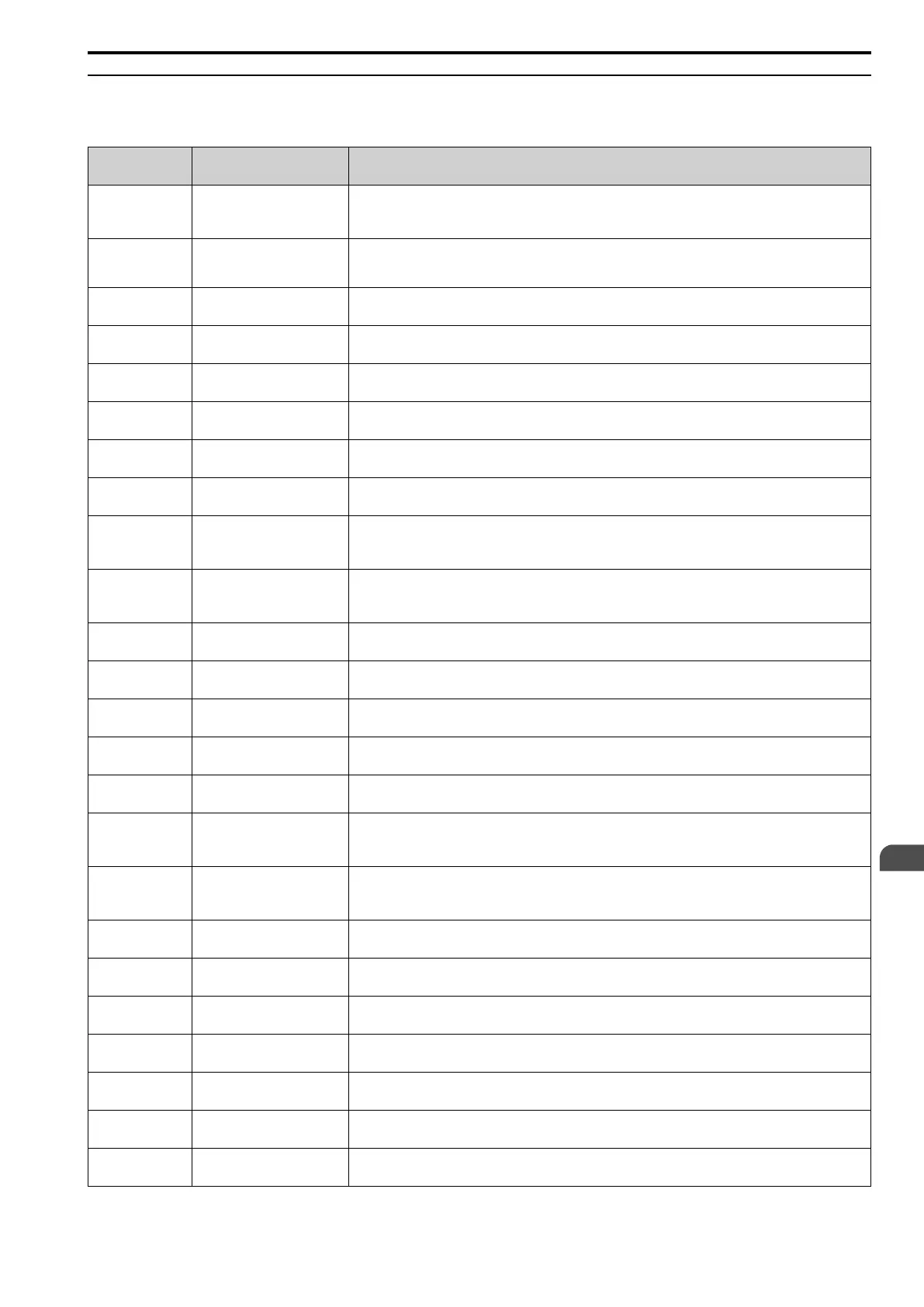
◆ Drive Parameters
This section shows the most common parameters for applications. Refer to this table when you set parameters.
No.
(Hex.)
Name Description
A1-00
(0100)
RUN
Language Selection Sets the language for the LCD keypad.
0: English, 1: Japanese, 7: Chinese
A1-02
(0102)
Control Method Selection Sets the control method for the drive application and the motor.
0: V/f Control, 1: V/f Control with Encoder, 2: Open Loop Vector, 3: Closed Loop Vector,
4: Advanced Open Loop Vector
A1-03
(0103)
Initialize Parameters Sets parameters to default values.
0: No Initialization, 1110: User Initialization, 2220: 2-Wire Initialization
A1-06
(0127)
Application Preset Sets the drive to operate in selected application conditions.
0: General-purpose, 1: Crane (Hoist), 2: Crane (Traveling), 3: Closed Loop Crane (Hoist)
b1-01
(0180)
Frequency Reference Selection 1 Sets the input method for the frequency reference.
0: Keypad, 1: Analog Input, 2: Memobus/Modbus Communications, 3: Option PCB
b1-02
(0181)
Run Command Selection 1 Sets the input method for the Run command.
0: Keypad, 1: Analog Input, 2: Memobus/Modbus Communications, 3: Option PCB
b1-03
(0182)
Stopping Method Selection Sets the method to stop the motor after removing a Run command or entering a Stop command.
0: Ramp to Stop, 1: Coast to Stop, 2: DC Injection Braking to Stop, 3: Coast to Stop with Timer
b1-04
(0183)
Reverse Operation Selection Sets the reverse operation function.
0: Reverse Enabled, 1: Reverse Disabled
C1-01
(0200)
RUN
Acceleration Time 1 Sets the length of time to accelerate from zero to maximum output frequency.
C1-02
(0201)
RUN
Deceleration Time 1 Sets the length of time to decelerate from maximum output frequency to zero.
C2-01
(020B)
S-Curve Time @ Start of Accel Sets the S-curve acceleration time at start.
C2-02
(020C)
S-Curve Time @ End of Accel Sets the S-curve acceleration time at completion.
C2-03
(020D)
S-Curve Time @ Start of Decel Sets the S-curve deceleration time at start.
C2-04
(020E)
S-Curve Time @ End of Decel Sets the S-curve deceleration time at completion.
C6-02
(0224)
Carrier Frequency Selection Sets the switching frequency (carrier frequency) for the transistors in the drive.
1: 2.0 kHz, 2: 5.0 kHz, 3: 8.0 kHz, 4: 10.0 kHz, 5: 12.5 kHz, 6: 15.0 kHz, F: User Defined (C6-03 to C6-05)
d1-01 - d1-15
(0280 - 0290)
RUN
Reference 1 to 15 Sets the frequency reference in the units from o1-03 [Frequency Display Unit Selection.
d1-17
(0292)
RUN
Jog Reference Sets the frequency reference in the units from o1-03 [Frequency Display Unit Selection]. Set H1-xx = 6 [MFDI
Function Select = Jog Reference Selection] to use the Jog frequency reference.
d2-01
(0289)
Frequency Reference Upper Limit Sets maximum limit for all frequency references. The maximum output frequency is 100%.
d2-02
(028A)
Frequency Reference Lower
Limit
Sets minimum limit for all frequency references. The maximum output frequency is 100%.
E1-01
(0300)
Input AC Supply Voltage Sets the drive input voltage.
E1-04
(0303)
Maximum Output Frequency Sets the maximum output frequency for the V/f pattern.
E1-05
(0304)
Maximum Output Voltage Sets the maximum output voltage for the V/f pattern.
E1-06
(0305)
Base Frequency Sets the base frequency for the V/f pattern.
E1-09
(0308)
Minimum Output Frequency Sets the minimum output frequency for the V/f pattern.
EN
 Loading...


