JOHNSON CONTROLS
100
FORM 102.20-N1
ISSUE DATE: 7/06/2016
SECTION 3 - HANDLING, STORAGE, AND INSTALLATION
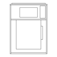
3. Using a moderate amount of pressure, force the
latch over the third knockout as shown in Figure
153 on page 100.
FIGURE 153 - CORRECTLY INSTALLED LATCH PIN
(P/N 026-35788-604)
LD10496
4. Grasp the loose end of the latch, and place it over
thepre-lterframe,sothatthe latch secures the
pre-ltertotheSHlter.
5. Repeat the process with the remaining latches.
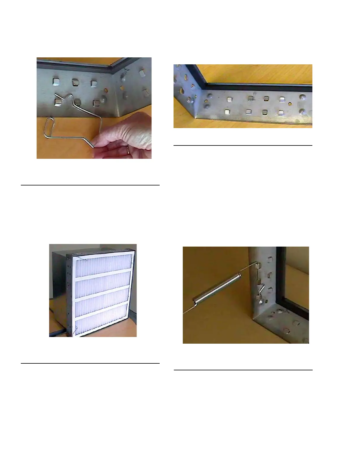
6. Thelters shouldnowbe securelyinstalledinto
the frame as shown in Figure 154 on page 100.
FIGURE 154 - CORRECTLY INSTALLED
CARTRIDGE WITH PLEATS
LD10160
Installing a Multi-Cell SBM Double Headered
(DH) Filter
Use the following instructions to install a Multi-Cell
SBM double header (DH) filter (nominal 12 in.) into a
16 g galvanized holding frame with four latches (P/N
026-35788-612), as shown in Figure 147 on page 95.
1. Install the two latches on each side of the frame.
not on the top or bottom. Refer to the sets of
knockouts in Figure 155 on page 100 that should
be used for the latches.
FIGURE 155 - CORRECT USE OF KNOCKOUTS
LD10150
2. Insert the straight end of the latch between the two
knockouts furthest from the corner.
3. Using a moderate amount of pressure, force the
latch over the third knockout.
4. The latch installation should be complete. The
latch should now be trapped within the three
knockouts.
5. Repeat the steps with the remaining latches. Note
the orientation of the latch to the knockouts as
shown in Figure 156 on page 100.
FIGURE 156 - CORRECT LATCHOUT/KNOCKOUT
CONFIGURATION
LD10154
6. After the latches are installed, the frame should be
conguredasshowninFigure 157 on page 101,
which shows there are two latches per side, none
on the top or bottom.

 Loading...