JOHNSON CONTROLS
62
FORM 102.20-N1
ISSUE DATE: 7/06/2016
SECTION 3 - HANDLING, STORAGE, AND INSTALLATION
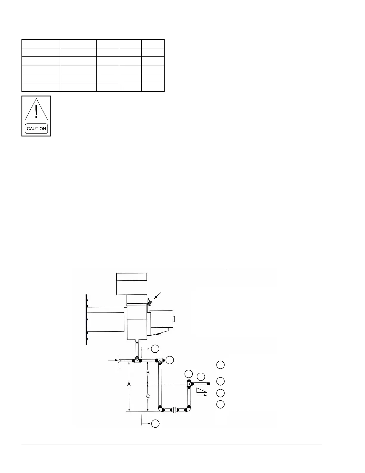
TABLE 2 - TSP AND DRAIN TRAP
MODEL DRAIN NPT A B C
DF-15/25 1/2 in. 4 in. 2 in. 2 in.
DF-30/50 1/2 in. 8 in. 4 in. 4 in.
DF-60/75 1 in. 8 in. 4 in. 4 in.
DF-85/200 1 in. 12 in. 6 in. 6 in.
DF-225/400 1 in. 16 in. 8 in. 8 in.
Failure to follow these instructions may
cause excessive condensation buildup,
resulting in water damage to the facility
and/or a cracked heat exchanger.
1. Observe local codes for gravity condensate drain-
age requirements.
2. Install the AHU at an elevation that enables prop-
er condensate drainage and trapping dimensions
as shown in Figure 97 on page 62. Minimum
trap dimensions MUST be accommodated.
3. The condensate drain line size must be the full
line size of the heat exchanger drain connection.
4. Drainlines,ttings,andsupportsshouldconform
to local codes, and be suitable for the application.
5. Condensate drain and trap discharge should be
pitched away from the equipment at a slope of 1/4
in. per linear foot or as local code dictates.
6. For outdoor or unconditioned space installations,
local climate may dictate the need to heat trace
and/or insulate the exposed drain lines and trap.
Frozen drain lines and/or trap will cause build up
of condensate inside the heat exchanger, resulting
in leakage and damage to the AHU, and possibly
to the building.
7. Provide unions in drain lines to allow removing
the trap for periodic cleaning of drain lines and the
trap. When the burner is operated at low capacity
for extended periods, more condensate is generat-
ed, and with it deposits of solids in the condensate
drainage system.
8. Provide the ability to prime the trap. During initial
and seasonal start-up, trap inspection and priming
is required. Condensate in the trap will evaporate
during long periods of non-use.
1
1
2
4
3
1
2
3
4
Foot
FIGURE 97 - GAS FURNACE CONDENSATE DRAIN TRAP
LD12912
BURNER ASSY
FLOW
PITCH
FIELD INSTALLED CONDENSATE
DRAIN PIPING - BY OTHERS
CLEAN OUT
WATER SEAL PRIME/ FILL
PITCH 1/4" / FOOT
ID
MOTOR

 Loading...