JOHNSON CONTROLS
101
SECTION 3 - HANDLING, STORAGE, AND INSTALLATION
FORM 102.20-N1
ISSUE DATE: 7/06/2016
3
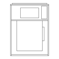
FIGURE 157 - FRAME WITH FOUR LATCHES
INSTALLED ON THE SIDES
LD10183
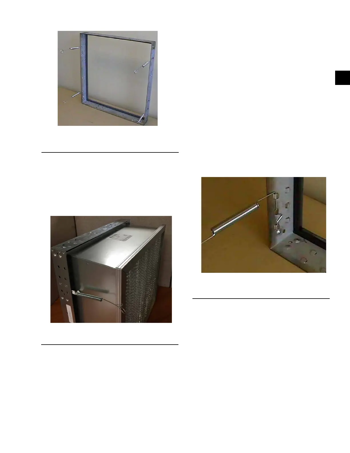
7. Insert the Multi-Cell SBM DH lter into the
frame.Whileholdingthelterintheframe,grasp
the loop on the end of the latch, and pull it until
it stretches over the header, and rests into the pre-
drilled hole in the header as shown in Figure 158
on page 101.
8. Repeat this step with the remaining latches.
LD10184
FIGURE 158 - SPRING LATCH PULLED AND
FASTENED IN FILTER HOLE
9. The lter should now be securely installed into
the frame.
Installing a 2 in. and 4 in. Pre-Filter Combined
with a DH Final Filter
Use the following instructions to install a 2 in or 4 in
Multi-Pleat Elite or MicroMAX pre-filter combined
with a Multi-Cell SBM DH (nominal 12 in. deep) final
filter into a 16 g galvanized holding frame. Use the fol-
lowinglatchestoinstallthelterandpre-lter:
• Four spring latches (P/N 026-35788-612) to hold
the Multi-Cell SBM DH into the frame,
• Four pre-lter latches (P/N 026-35788-625) to
hold the 2 in. latch, and
• Four pre-lter latches (P/N 026-35788-626) to
holdthe4inpre-lterontothefaceoftheMulti-
CellSBMDHlter.
1. Install the two latches on each side of the frame,
not on the top or bottom.
2. Insert the straight end of the latch between the two
knockouts furthest from the corner.
3. Using a moderate amount of pressure, force the
latch over the third knockout.
4. The latch installation should now be complete.
The latch should now be trapped within the three
knockouts as shown in Figure 159 on page 101.
FIGURE 159 - CORRECT LATCHOUT/KNOCKOUT
CONFIGURATION (P/N 026-35788-612)
LD10154
5. Repeat the steps with the remaining latches. Note
the orientation of the latch to the knockouts as
shown in Figure 159 on page 101.
6. Insert the Multi-Cell SBM DH lter into the
frame.Whileholdingthelterintheframe,grasp
the loop on the end of the latch, and pull it until
it stretches over the header, and rests into the pre-
drilled hole in the header as shown in Figure 160
on page 102.

 Loading...