JOHNSON CONTROLS
30
FORM 102.20-N1
ISSUE DATE: 7/06/2016
SECTION 3 - HANDLING, STORAGE, AND INSTALLATION
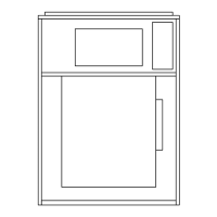
TOOLS REQUIRED TO INSTALL AHU
The following tools, which are not provided by John-
son Controls, are needed to install the AHU. Refer to
Figure 21 on page 30 for more information.
• Drill with adjustable torque
• No. 3 Phillips bit
• Allen wrench set
• Nut setter or socket set (1/4 in., 5/16 in., 3/8 in.
and 9/16 in.)
• Wire cutters
• Come-a-longs (power pulls)
• Slings
• Pry bar
• Drift pins and awls
• Common hand tools
• Caulking gun
• Shackles
FIGURE 21 - TOOLS NEEDED TO ASSEMBLE
SHIPPING SPLITS
LD09613
When the AHU is shipped in skids, re-
place the curb gasket with the the caulk
provided by the contractor because gas-
kets on curbs can pose a problem when
sliding skids together for the nal con-
nection of each shipping split.
SHIPPED LOOSE PARTS
The shipped loose parts, which may be required, are
shown in Figure 22 on page 30 through Figure 38
on page 33. Installation instructions for the shipped
loose parts are listed on the Installation Instructions
and Ship Loose Items Inside label, located on the ac-
cess door of the first fan skid in the air stream.
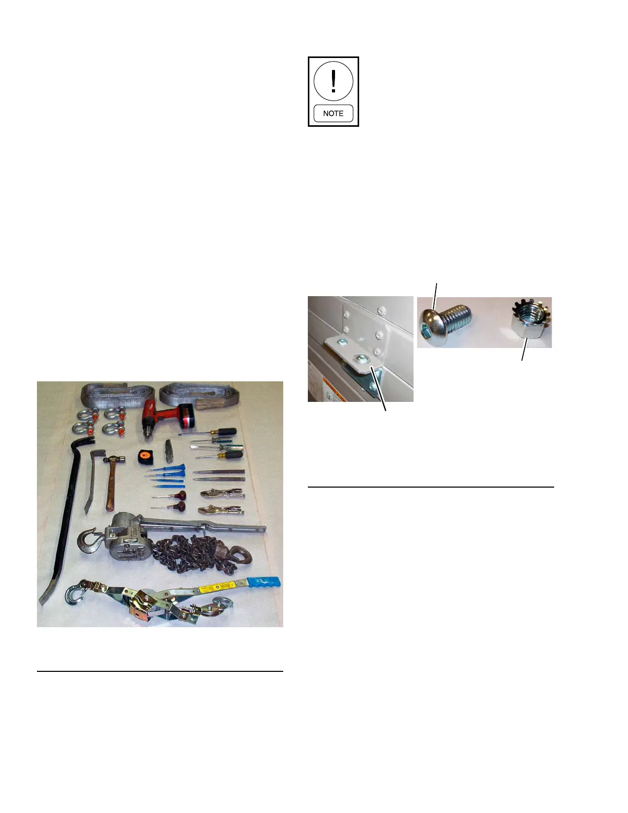
3/8 in. Lock Nut
Head Screw
3/8 x 3/4 in. Button
Head Screw
FIGURE 22 - SECOND TIER TIE-DOWN FASTENER
PACK (P/N 386-03419-000)
LD11029a

 Loading...