JOHNSON CONTROLS
71
SECTION 3 - HANDLING, STORAGE, AND INSTALLATION
FORM 102.20-N1
ISSUE DATE: 7/06/2016
3
If it is incorrectly installed, remove the two screws
holding the pressure probe in place and rotate 180°
and reinstall. The airflow switch pressure port that is
not connected to this pressure probe will be run to the
exterior of the AHU to source a reference differential
pressure.
In some situations it may be necessary to adjust this
airflow switch setting to allow for proper operation as
shown in Figure 109 on page 70. Take precautions
to make sure that the airflow switch does not indicate
false airflow.
Visually inspect the heater elements, prior to using the
heater. If physical damage is evident, use a megohm
test to validate the heater elements are safe use. If a
minimum value of 10 megohms is not achieved, then
any damaged elements or ceramic insulators must be
replaced, prior to operation.
Electrical Installation
1. Follow the wiring diagram on the inside of the ter-
minal box.
2. Make supply connections with copper wiring rat-
ed for 75°C minimum.
3. If supply connections are for 250 volts or greater,
all wiring must be insulated for 600 volts.
4. When making line connections to heater element
terminalsfornnedtubularheatersonly,applya
1/4in.wrenchtotheatsectionof theterminal
immediately below threads. Otherwise, damage to
the terminal may result.
5. Size supply conductors for heaters rated less than
50 kW at 125% of rated load. On heaters rated
50 kW and greater, size the supply conductors at
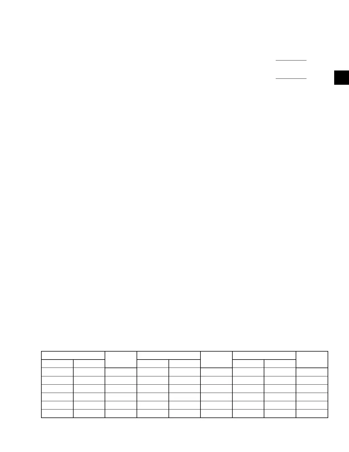
TABLE 3 - MAXIMUM CURRENT
AMPS
WIRE SIZE
AWG/MCM
AMPS
WIRE SIZE
AWG/MCM
AMPS
WIRE SIZE
AWG/MCM
125% 100% 125% 100% 125% 100%
12 14 80 100 3 184 230 4/0
16 12 92 115 2 204 255 250
24 10 104 130 1 228 285 300
40 8 120 150 0 248 310 350
52 65 6 140 175 2/0 268 335 400
68 85 4 160 200 3/0 304 380 500
100% of rated load, if indicated on the wiring dia-
gram. The line current for a single or three phase
load is calculated as follows:
kW x 1000
Voltage
Single Phase
Line Current =
kW x 1000
Voltage x 1.73
Three Phase
Line Current =
6. Table 3 on page 71 shows the maximum cur-
rent for 75°C copper wire with no more than three
conductors in a raceway, which is based on the
NEC - Table 310-16. The amperages are 125%
and 100% wire sizes. If there are more than three
conductors in a raceway, de-rate these amperages
per Table 3 on page 71.
When connecting heaters with more than one stage,
wire stage No. 1 so that it is the first stage on, and the
last stage off.
7. Wire the heater so that it cannot operate unless air
isowingoverit,whichcanbeaccomplishedby
usingabuilt-inairowswitchandaremoteinter-
lock. See the wiring diagram located inside of the
electric heater control panel for the method used
with the heater and provide appropriate interlock
wiring as illustrated.
8. If not supplied as part of the heater, install a line
disconnect switch or main circuit breaker in ac-
cordance with the NEC. Depending upon the
heater’s location and accessibility, a built-in dis-
connect switch may meet this requirement.
9. Check all electrical connections in the heater, in-
cludingbotheldandfactorymadeconnections,
for tightness before operating the heater. After a
short period of operation, check all connections
again for tightness.

 Loading...