JOHNSON CONTROLS
102
FORM 102.20-N1
ISSUE DATE: 7/06/2016
SECTION 3 - HANDLING, STORAGE, AND INSTALLATION
LD10184
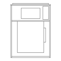
FIGURE 160 - SPRING LATCH PULLED AND
FASTENED IN FILTER HOLE
Installing Pre-Filter Latches
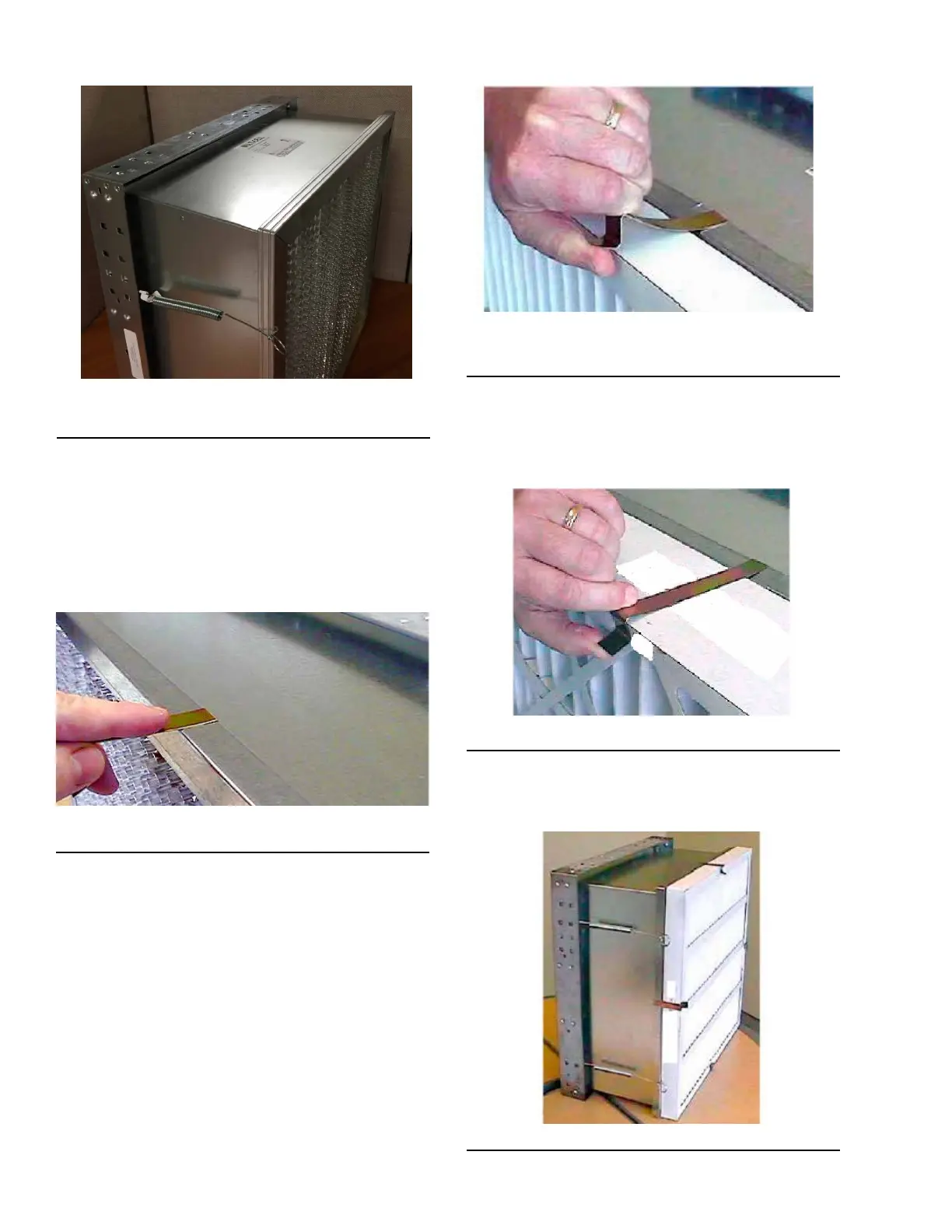
1. Toinstallthepre-lterlatches,slidetheendofthe
latch with a 180° turn over the edge of the header,
as shown in Figure 161 on page 102. Install the
latchattheapproximatemidpointofthelterleg.
Thepre-lterlatchshouldbeslidovertheheader
as shown in Figure 161 on page 102.
FIGURE 161 - INSTALLING PRE-FILTER LATCH
LD10163
2. Repeat the steps for the remaining pre-lter
latches.
3. Placethepre-lteragainstthefaceoftheMulti-
Cell SBM DH lter. The pre-lter latches may
have to be re-positioned as shown in Figure 162
on page 102, to allow the proper placement of
thepre-lter.
FIGURE 162 - POSITION PRE-FILTER IN FRONT
OF FINAL FILTER
LD10165
4. Grasp the end of the pre-lter latch and spring
it,sothatittsovertheedgeofthepre-lteras
shown in Figure 163 on page 102.
5. Repeat this step with the remaining latches.
FIGURE 163 - SPRING END OF LATCH
After placing all remaining pre-filter latches around
the pre-filter; the finished assembly should look like
the one shown in Figure 164 on page 102.
FIGURE 164 - COMPLETED ASSEMBLY
LD10167
LD10190

 Loading...